
LYNK Network Communication Cables
NOTICE |
EQUIPMENT DAMAGE
Failure to follow these instructions may result in equipment damage. |
Networking Guidelines
Separate data and power cables allow for separation between data and power cables. Avoid interference and data corruption caused by running network cables bundled with power cables.
Allow for LYNK Network cable slack. Ensure that LYNK Network cables are slack and not in tension.
Isolate the LYNK Network. Do not mix other networks with the LYNK Network.
NOTE |
|---|
The LYNK II Communication Gateway is internally terminated. A termination resistor is not required. |
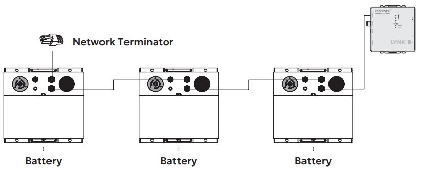
LYNK (AEbus) Network Installation and Layout for AES LiFePO4 batteries (42-48-6650)
Insert one end of a CAT6 or higher cable into the LYNK Port (RJ45) on the LYNK II. Insert the other end of the cable into the AEbus Port located on the AES LiFePO4 battery. If there are multiple AES LiFePO4 batteries, series network (daisy-chain) them together and insert the end of the cable from LYNK II into the AEbus Y-Connector at the end of the network, as shown below. The LYNK II Communication Gateway is terminated internally. Termination at the opposite end of the LYNK (AEbus) network is also required.
LYNK Network Installation and layout
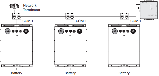
LYNK (AEbus) Network Installation and Layout for AES LiFePO4 batteries (14-36-3000, 14-48-3000, 44-48-3000)
Insert one end of a CAT6 or higher cable into the LYNK Port (RJ45) on the LYNK II. Insert the other end of the cable into the AEbus Port located on the AES LiFePO4 battery. If there are multiple AES LiFePO4 batteries, network them together in a daisy chain. Connect the cable from LYNK II to the AEbus Port of the battery at the end of the network, as shown below. The LYNK II Communication Gateway is terminated internally. Termination at the opposite end of the LYNK (AEbus) network is also required.
LYNK Network Installation and layout for AES 3K models
LYNK Network Installation and Layout for AES PROFESSIONAL batteries
Mount the devices according to their installation instructions before beginning network installations.
Attach the 950-0038 DLP T Connector to the LYNK Port on each battery. Ensure that the mating connectors are securely fastened.
Insert the male end of the cable into the female end of the 950-0038 DLP T Connector and vice versa.
Repeat until all batteries have been attached in a series network.
Attach one end of the series network to the LYNK Port on LYNK II. Termination of the other end is not required.
LYNK Network Cables Available for AES PROFESSIONAL Batteries | Part Number |
|---|---|
DLP B2B-400 (COMM Cable 0.4 m) | 950-0035 |
DLP TOL-7600 (COMM Cable 7.6 m) | 950-0037 |
DLP TOL-1800 (COMM Cable 1.8 m) | 950-0036 |
DLP T Connector (COMM T Connector) with DLP B2B-400 (COMM Cable 0.4 m) | 950-0038 |
DLP T Connector (COMM T Connector) | 950-0041 |
Attaching DLP T Connector to LYNK Port
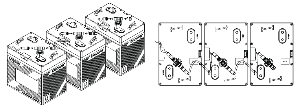
Completed Network Installation
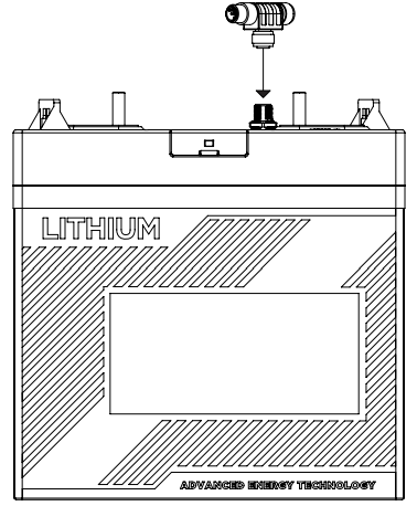
LYNK Network Installation and Layout for AES RACKMOUNT batteries
Using a CAT6 or higher cable, insert one end into the LYNK Port (RJ45) on the LYNK II. Insert the other end of the cable into the LYNK Port located on the AES RACKMOUNT battery. If there are multiple AES RACKMOUNT batteries, insert CAT6 or higher cables to daisy-chain the batteries together. No extra termination is required as the LYNK II Communication Gateway and AES RACKMOUNT batteries are terminated internally.
Mount the devices according to their installation instructions before beginning network installations.
Attach CAT6 or higher cables to the LYNK Port, from one battery to the next battery, until all the batteries are connected to form a series network.
If you are using the Battery Module Combiner, also attach a CAT6 or higher cable from one of the batteries to the LYNK Port on the Battery Module Combiner.
At the end of the network, attach a CAT6 or higher cable from either the battery or the Battery Module Combiner to the LYNK Port on the LYNK II.
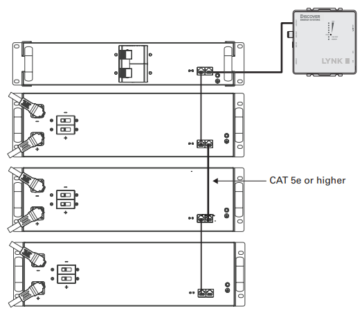
LYNK Network Installation for AES RACKMOUNT
LYNK Network Installation and Layout for HELIOS ESS batteries
Using a CAT6 or higher cable, insert one end into the LYNK Port (RJ45) on the LYNK II. Insert the other end of the cable into one of the LYNK Ports (COM3/ COM4) located on the HELIOS ESS battery. If paralleling multiple HELIOS ESS batteries, attach CAT6 or higher cables to the COM3/COM4 ports to daisy chain all the batteries together.
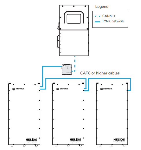
LYNK Network Installation for HELIOS ESS
NOTE |
|---|
HELIOS ESS Batteries prior to serial number DLPHD48B251820001 are supplied with a termination resistor. When setting up closed-loop communication with these HELIOS ESS batteries, plug the termination resistor into the COM3/COM4 port on the last battery in the LYNK network and update the battery firmware. |