
Drain and Refill TMS Coolant
STEP 1: Preparation
Power down the AES Cabinet system.
Engage E-Stop and confirm 0 Vdc on HV terminals.
Disconnect the auxiliary 240 Vac input to the cabinet.
Remove all Manual Service Disconnects (MSD).
Tag the system as “De-energized – Maintenance in Progress.”
STEP 2: Coolant Drain and System Depressurization
Basic gravity drain (recommended for routine maintenance)
Connect Recovery Lines
Attach drain line to the coolant inlet port
Attach overflow line to the overflow/exhaust port (highest point in coolant loop)
Route both hoses to a coolant recovery container
Open Valves
Open the inlet port valve and the overflow/exhaust port valve
Ensure overflow port remains vented to atmosphere to avoid vacuum lock
Gravity Drain
Allow coolant to drain naturally from the system
Monitor recovery container to avoid overflow
Optional: Complete Drain (for Full System Evacuation)
Vacuum tool on inlet port line to recover any residual fluid
Use a drain pan and disconnect the lowest coolant connection on the chiller plate of the bottom battery pack. Use care to avoid damage to the coolant line connector.
NOTE |
|---|
|
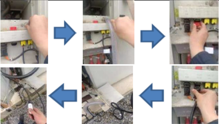
STEP 3: Disconnect Electrical and Communication Lines
Label and disconnect:
24 V pump power
AC main power (L-N-PE)
CAN communication line
Disconnect the TMS grounding from the cabinet chassis.
Confirm all connectors are clean and protected with caps or covers.
STEP 4: Glycol Preparation
A. Prepare the Equipment
Confirm system is powered down and depressurized.
Place coolant catch basin beneath cabinet.
Remove protective caps from the coolant injection port and exhaust port.
Connect the power supply to the fill pump, but do not activate yet.
B. Connect the Overflow Line
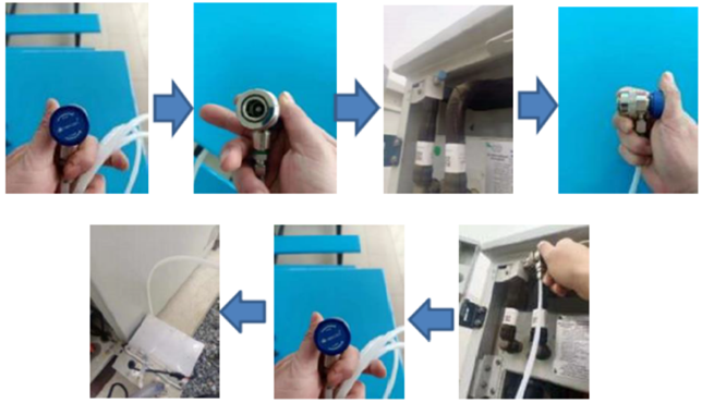
Rotate the blue quick coupler knob counterclockwise to release the valve pin.
Attach the Overflow Line to the chiller’s exhaust port at the top-most point of the plumbing.
Rotate the coupler knob clockwise to engage and open the internal valve.
Route the transparent drain tubing to the return container.
C. Connect the Fill Tool
Remove the cap from the unit’s coolant fill port.
Attach the fill line (with quick-connect).
Connect the fill pump’s power control switch and ensure coolant is loaded in the reservoir.
STEP 5: Glycol Filling Process
A. Prime the TMS
Power on the TMS control panel (small debugging display).
Activate the self-circulation mode on the unit.
Do not start active cooling or heating during filling.
B. Begin Filling
Open the valve on the coolant fill pipe.
Activate the fill pump using its power control switch.
Observe the Overflow line for air bubbles.
C. Monitor and Vent
Continue filling for 30 minutes.
Watch for bubbles exiting through the Overflow line; do not stop until all air is cleared.
D. Final Fill & Pressure Stabilization
Once bubbles are gone, close the exhaust valve and disconnect the exhaust tool.
Continue filling for an additional 10 to 20 seconds.
Monitor the coolant pump outlet pressure:
Target: ≥3.9 bar (operational goal: ~4.0 bar)
Once pressure is stable:
Close the internal fill line valve.
Shut off the fill pump via power switch.
E. Balance Check
After 15 seconds, observe system balance pressure:
Acceptable: ≥2.6 bar
Optimal: ~2.7 bar
NOTE |
|---|
If pressure is below 2.6 bar, repeat the filling process until proper system pressure is achieved. |
STEP 6: Power-up and Functional Verification
Disconnect the fill tool and seal the fill port.
Inspect all fittings and lines for leaks.
Wipe down any spilled fluid.
Reapply auxiliary power and restore MSDs.
Power on inverter and cabinet.
Verify:
TMS startup (coolant pump, fan, compressor or heater based on temperature)
No fault codes or alarms
Coolant temperatures stabilize at setpoints (Cooling: 20°C / 68°F, Heating: 30°C / 86°F)
Run TMS auto-test or force cooling/heating modes for final validation.
Documentation and Handoff
Record:
TMS serial number (replaced unit)
Coolant batch/lot number
Operating pressures at commissioning
Time/date of service and technician signature