AES Cabinet Faults and Warnings
This guide is intended for qualified service professionals. It covers common fault types, diagnostic strategies, and required clearing methods for faults and warnings in the AES-CAB system.
🔴 Critical Faults (Manual or Power Cycle Reset Required)
These faults typically shut down the PCS or system. Immediate attention is required.
Fault | Cause | Clearance Method | Action |
|---|---|---|---|
AC Bus Short Circuit | Fault in AC cable or PCS component | Manual reset / Repair (FM) | Inspect AC wiring, call support if persistent. |
DC Input Overvoltage | Battery voltage exceeds max allowable | Power Cycle (FP) | Check cluster voltage, verify battery configuration. |
DC Input Undervoltage | Battery voltage below min threshold | Power Cycle (FP) | Check battery charge state or replace damaged battery packs. |
Emergency Shutdown (EPO Triggered) | EPO circuit triggered | Manual reset (FM) | Inspect and reset EPO circuit. |
Fan Failure (Internal or External) | Fan not operating | Manual (FM) | Verify terminal connections; replace fan if failed. |
Internal Over-Temperature | Inverter overheated | Manual reset (FM) or contact OEM | Check airflow, clean or replace fans. |
Lightning Protection Fault (AC/DC) | Surge protection devices failed | Manual (FM) | Inspect SPD modules and terminal tightness. |
Module Over-Temperature | IGBT module temperature too high | Manual (FM) | Inspect module cooling, check heat sink contact. |
Soft Start Failure | Pre-charge circuit failure | Manual (FM) | Power down, inspect relay and board. |
🟡 Self-correcting or Low-priority Faults
These faults are automatically cleared once conditions normalize. No manual intervention is typically required.
Fault/Warning | Cause | Clearance Method | Action |
|---|---|---|---|
AC Bus Overvoltage / Under voltage | Grid voltage out of range | Auto (FA) | Wait for grid normalization. |
AC Frequency Over/Under | Grid frequency deviation | Auto (FA) | Wait for frequency to stabilize. |
DC Bus Overvoltage/Under voltage | DC link cap voltage out of range | Auto (FA) | Monitor inverter, battery voltage. |
Frequent Start-Stop | Repeated PCS cycling | Auto or Manual | Review EMS scheduling strategy. |
Low Battery Energy | BMS low SOC trigger | Auto (FA) | Charge battery |
Parameter Mismatch | Inverter config issue | Auto (FA) | Review and correct parameter settings |
🔁 Fault Clearing Codes
FA: Fault + Auto-clear
FM: Fault + Manual Clear
FP: Fault + Requires Power Cycle
AA: Alarm + Auto-clear
WA: Warning + Auto-clear
WM: Warning + Manual Clear
⚙️ Installer Troubleshooting Steps
Check Indicators
POWER OFF: No input power — verify AC and DC inputs
RUN OFF: Inverter not running — check DC start voltage and AC sync
FAULT ON: Persistent issue — check logs and LCD for fault code
Initial Checks
Verify correct DC battery voltage
Check AC phase voltage and neutral wiring
Inspect ground connections
Confirm communication (BMS ↔ PCS, EMS ↔ PCS)
Clear Alarms
Use HMI/web interface to view current alarms
For manual reset, issue reset via software or hardware control
For power cycle faults, fully shut down the inverter (AC/DC), wait 5 minutes, restart
Document Fault
Note the time, site, inverter serial, system state, and capture screenshots if possible
Export logs from the web interface when needed
Call Support When:
Hardware damage is suspected (fan failure, lightning arrestor, internal over-temp)
Fault recurs more than 5–10 times per day
Communication to BMS or EMS consistently fails
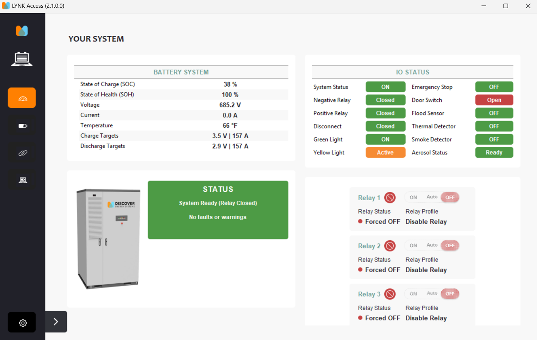
LYNK ACCESS Views
How the system dashboard in LYNK ACCESS should look when everything is working correctly.
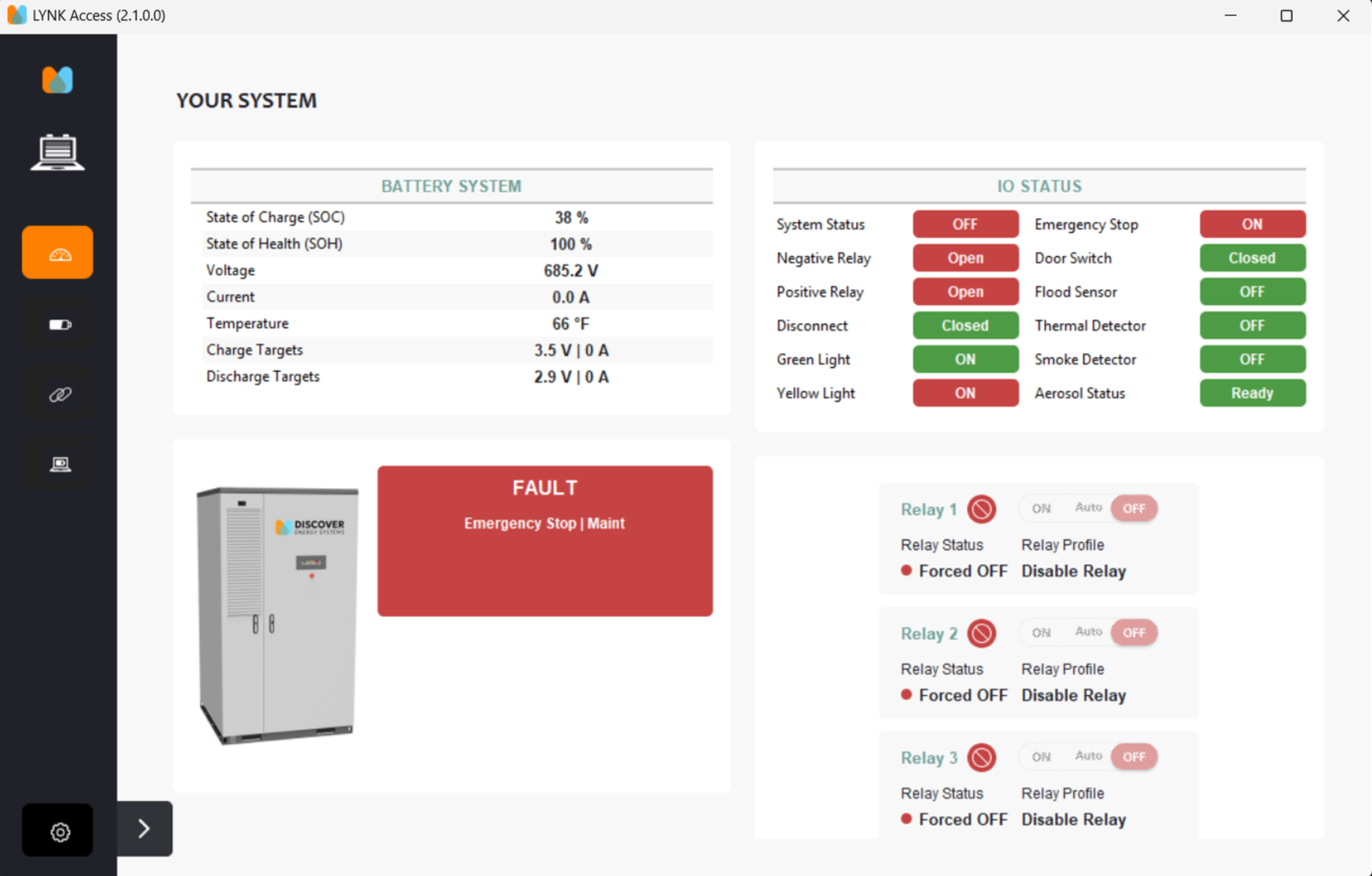
System Dashboard when the E-Stop button is depressed and activated.
Error if the door is not closed properly or the door switch mounting bracket is bent and not allowing the switch to be depressed.