
Setting Managed (Closed-loop) Configuration on the Selectronic Inverter-Charger
After selecting the Selectronic communication protocol for the LYNK II, complete the managed (closed-loop) configuration settings on the Selectronic inverter-charger. Ensure the Discover Lithium Batteries are networked with LYNK II and that the LYNK II is connected to the Selectronic CAN port.
Managed (Closed-loop) Configuration
Refer to the latest Discover Energy Systems documentation for battery values and the latest Selectronic documentation for menu navigation and details on the setup procedure.
All values and parameters assume an operating temperature of 25 °C (77 °F).
Set the Discover Lithium batteries to ON and set the inverter-charger to ON.
Install and then start the latest version of the SP LINK application.
From the File menu, select Site Information > New (Easy Start Guide).
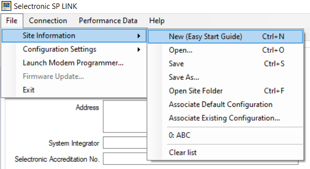
File > Site Information > New (Easy Start Guide)
In the Easy Start Guide, click Site Configuration Wizard.
In the New Site Connection Details page, enter the site name and specify the inverter-charger.
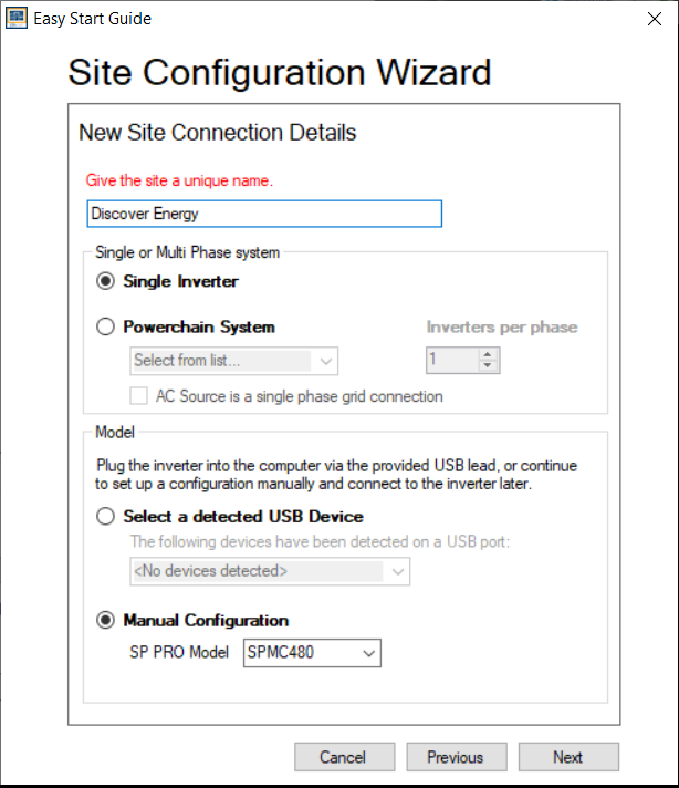
New Site Connection Details
In the Select Battery Configuration page, select the Standard Battery Configurations and myGrid kits option.
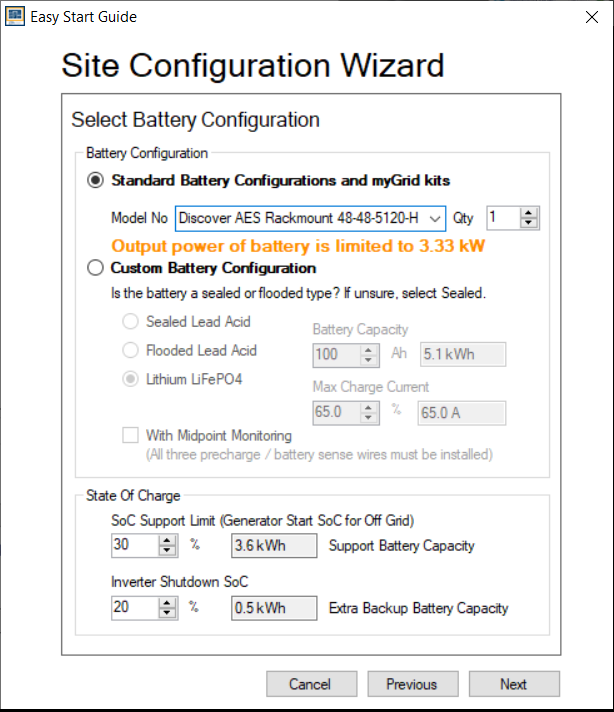
Select Battery Configuration
For the battery Model No, select either Discover AES Rackmount 48-48-5120-H or Discover HELIOS ESS 52-48-16000 and accept the defaults.
In the Source of Renewables page, define the solar panels of the system.
In the Select Unit Application page, define how to use the energy stored in the batteries.
In the AS/NZS 4777.2 Compliance page, identify the region of the installation.
In the Extra Options page, select other options used by the solar and energy storage system.
In the Summary of settings, review the configuration and click Finish.
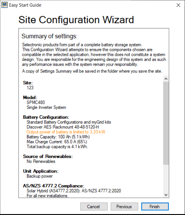
Summary of Settings
Follow the wizard’s instructions to complete the setup.
Configuration Settings
By selecting either Discover AES Rackmount 48-48-5120-H or Discover HELIOS ESS 52-48-16000 from the SP-Link wizard, it populates the Configuration Settings with the default values.
Confirm the default values are suitable for your installation.
NOTICE |
|---|
BATTERY DAMAGE
Failure to follow these instructions may result in equipment damage. |
Click the Configuration Settings tab and review all the settings in the Inverter, Battery, and Charger sub tabs.
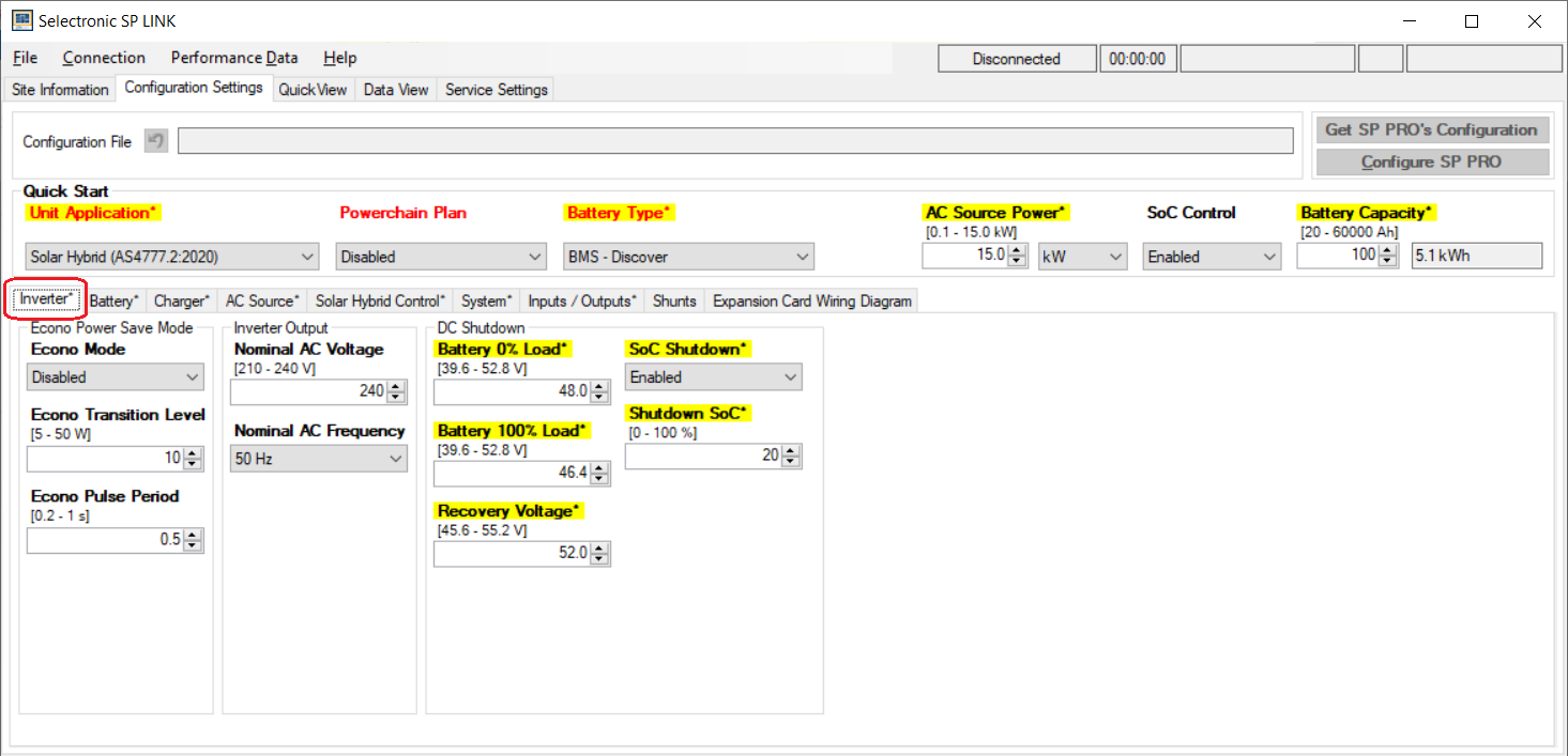
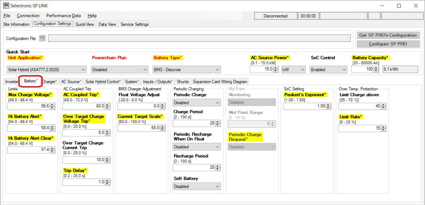
Inverter, Battery, and Charger sub-tabs
In the battery settings, confirm the Battery Capacity and Current Target Scale.
Property | AES RACKMOUNT | HELIOS ESS |
|---|---|---|
Current Target Scale | 65% | 48% |
Battery Capacity | Number of batteries x 100 Ah | Number of batteries x 314 Ah |
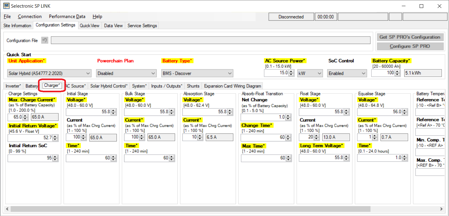
In the charger settings, confirm the Max Charge Current and Current at the various charge stages (Initial, Bulk, Absorption, and so on).
Property | AES RACKMOUNT | HELIOS ESS |
|---|---|---|
Max Charge Current | 65% | 48% |
Review all the other settings.
Once the configuration is complete, from the File menu, click Configuration Settings > Configure SP Pro to send the project to all assigned SP PRO inverter-chargers.
NOTICE |
|---|
NOTICE |
|---|
EQUIPMENT DAMAGE
Failure to follow these instructions may result in equipment damage. |