
Electrical Wiring
|
|---|
ELECTRIC SHOCK HAZARD
Failure to follow these instructions may result in death or serious injury. |
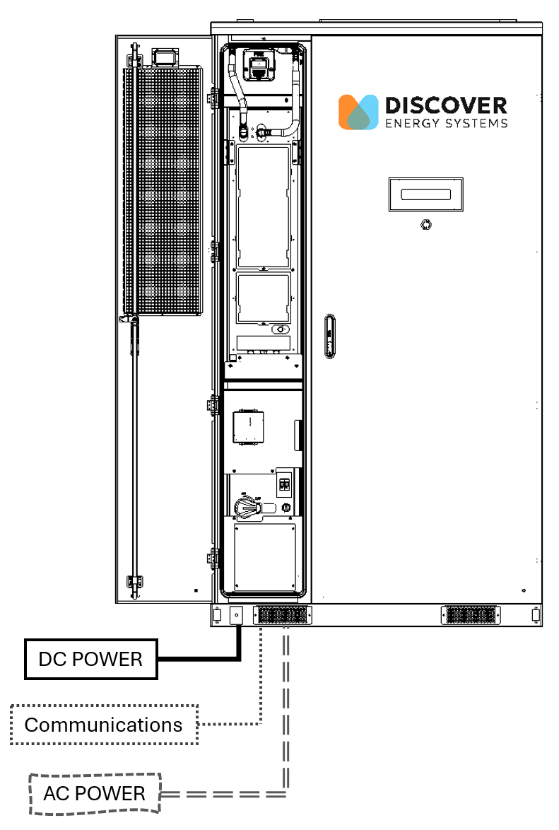
Electrical Wiring Overview
The battery system requires dedicated connections for DC power, auxiliary AC power, LYNK communication, internet, and grounding. For safety and to prevent interference, route DC, AC, and communication cables in separate conduits.
DC Conductors: Terminate DC connections at the HV Box. Conductors must be properly sized based on the PCS specifications and fuse rating (connection is rated for 200 A).
AC Input: Connect AC input cables to the AUX AC wiring assembly, using two conductors plus a ground wire, rated for 30 A at 240 Vac (single-phase).
Communication: Use two Unshielded Twisted Pair (UTP) cables—one for CANbus communication with the inverter and one for the internet connection to the LYNK II Gateway.
Grounding: Connect the system to a dedicated ground rod or Ufer ground for proper grounding and safety compliance.
NOTICE |
|---|
COMMUNICATION CABLE DAMAGE
Failure to follow these instructions may result in equipment damage. |
NOTICE |
|---|
DO NOT PARALLEL BATTERY CABINETS ON THE DC BUS Do not parallel the AES battery cabinets on the DC bus. Attempting to connect multiple cabinets in parallel on the DC bus may result in unbalanced currents, system instability, or potential damage to the equipment. Failure to follow these instructions may result in equipment damage. |
Connecting the DC outputs of battery cabinets in parallel is not supported. The AES battery cabinets are designed to operate as independent units, each with its own DC connections to the inverter DC inputs/outputs. Attempting to connect multiple cabinets in parallel on the DC bus may result in unbalanced currents, system instability, or potential damage to the equipment.