
SYSTEM OVERVIEW
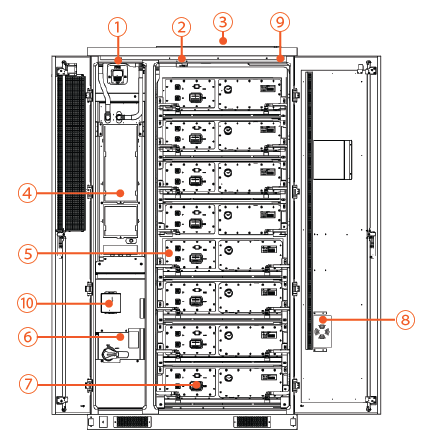
AES Cabinet, Front Doors Open
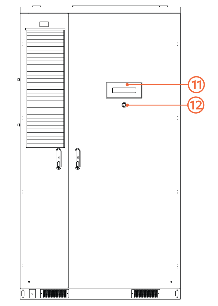
AES Cabinet, Doors Closed
No. | Name | Description |
|---|---|---|
1 | Audible and Visual Fire Alarms | In the event of a fire hazard, the battery cabinet activates the thermal suppression device and sounds an alarm. See Thermal Suppression System for details. |
2 | Heat and Smoke Detector | Smoke detection triggers an alarm, while heat detection activates an alarm and the thermal suppression system. |
3 | Passive Deflagration Vent | Explosion control vents relieve pressure during thermal events by venting gases, which helps minimize the risk of explosion. |
4 | Thermal Management System (TMS) | The TMS manages heating and cooling for the battery cabinet. |
5 | Battery Packs | Energy storage units with integrated cell monitoring via the Battery Management Unit (BMU). Each pack features an aerosol fire suppression system and aerogel-based cell separation, ensuring advanced thermal runaway mitigation. |
6 | High Voltage Box (HV Box) | The HV Box manages power flow, protects the system, provides redundant control via UPS, and monitors the system through the Battery Control Unit (BCU). For information on the High-Voltage Battery box, see High Voltage Box (HV Box). |
7 | Manual Service Disconnect (MSD) | Each battery pack is equipped with a Manual Service Disconnect (MSD). |
8 | Dehumidifier | The humidifier maintains humidity inside the sealed battery cabinet at an acceptable level. |
9 | Cabinet Aerosol Fire Suppression Device | If a high heat event is detected, the aerosol fire suppression system is automatically activated to quickly release an aerosol fire suppression agent. |
10 | LYNK II Gateway | The LYNK II Gateway facilitates communication between the battery cabinet BCU and external devices, such as inverters or cloud-based systems. |
11 | LED Indicators | The LEDs indicate the system operation status:
|
12 | E-Stop | Emergency stop switch for manual shutdown of the battery cabinet. |