
Installing the Conduit Box
|
|---|
INSTALLATION HAZARDS
Failure to follow these instructions may result in injury. |
Prepare the conduit box. If installing multiple HELIOS ESS batteries with conduit boxes, plan on drilling holes on the sides for passing wires and cables between conduit boxes with batteries.
The diagram below is an example of the possible hole positions and sizes.
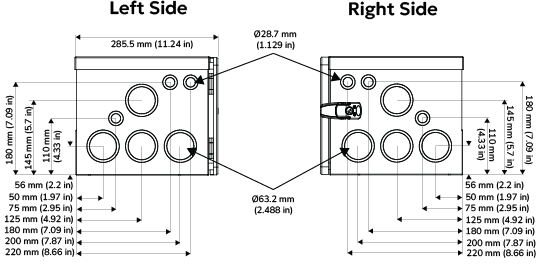
Example Size and Side Location of Holes (Ø63.2 mm [2.488 in], Ø28.7 mm [1.13 in])
Depending on the installation plan, holes may not be required on both sides of a conduit box, or may not be required at all.
On the top side of the conduit box, drill holes for the positive and negative inverter cables and the CAN communication cable. Please verify the hole sizes and positions required by the inverter. The diagram below is an example of the possible hole positions and sizes.
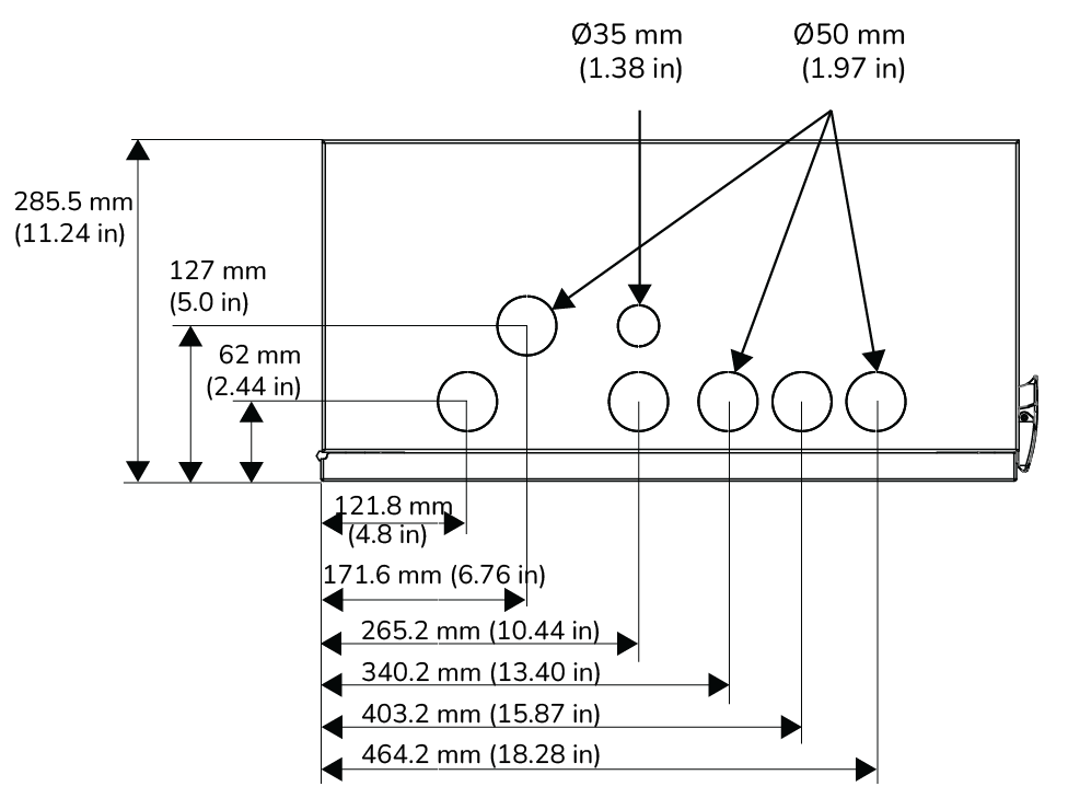
EXAMPLE Size and Top Location of Holes (Ø50 mm [1.97 in], Ø35 mm [1.38 in])
NOTICE |
|---|
EQUIPMENT DAMAGE The generic conduit box does not have venting. When installing an inverter with the conduit box, do not block the inverter’s fans and air vents. Failure to follow these instructions may result in equipment damage. |
The following instructions are for installing the HELIOS ESS battery, Conduit Box, and inverter against a wall.
Use a stud finder to locate the wall studs.
Identify a location that optimizes usability and support for the inverter and battery. The battery’s Wall-Mount Bracket requires at least 4 bolts supported by wall studs.If the wall studs are not in ideal locations, consider adding appropriate structural supports to spread the weight of the 130 kg (286.6 lb) battery and the inverter.
Mark the location of holes for the battery and inverter wall-mount brackets.
Verify the hole marks are level, at the correct height, and in an appropriate location against the wall.
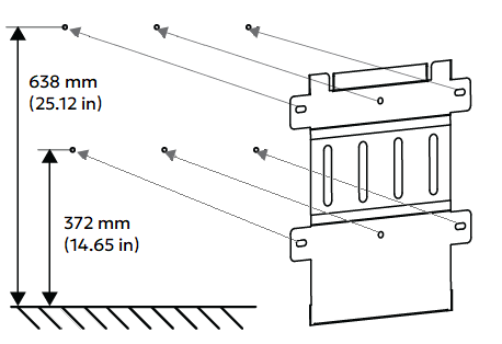
HELIOS ESS Battery Wall-Mount Bracket
Drill the holes for screws of the HELIOS ESS battery’s wall-mount bracket and holes for the screws that will hold the inverter in place.
Secure the HELIOS ESS Wall-Mount Bracket to the wall using appropriate fasteners that can support the battery’s weight and are compatible with the material of the wall or studs.
Attach the HELIOS ESS battery to the Wall-Mount Bracket. Refer to the HELIOS ESS Installation and Operation Manual (805-0090) for instructions.
On the top of the HELIOS ESS battery, unscrew the four conduit box mounting screws.
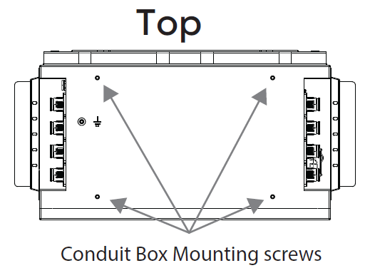
Place the HELIOS ESS Generic Conduit Box on top of the battery and affix to the battery with the mounting screws.
Attach the inverter to the wall. Refer to the inverter manufacturer’s documentation for installation instructions.
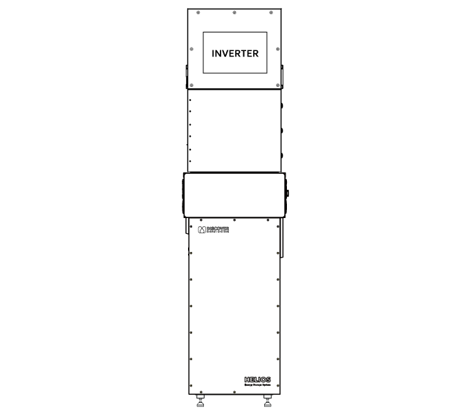
Example Inverter and Conduit Box installed on the HELIOS ESS battery
Next, wire the batteries and the inverter.