
Capacity and Configuration (Paralleling)
NOTICE |
|---|
EQUIPMENT DAMAGE Do not parallel AES Cabinets on the DC bus. Attempting to parallel the DC outputs of individual battery cabinets can result in unbalanced currents, system instability, or potential damage to the equipment. Failure to follow these instructions may result in equipment damage. |
Do Not Parallel Battery Cabinets on the DC Bus
Each AES Cabinet is designed to operate independently and must connect to a dedicated inverter input. Do not combine or parallel the DC outputs of multiple cabinets, as this will result in unbalanced current flow, system instability, and equipment damage.
Parallel Inverters on the AC Bus
System scalability is achieved by paralleling inverters on the AC bus, not by paralleling the batteries. Each inverter has a dedicated battery cabinet in this design, and the inverter AC outputs are synchronized to support larger system loads. This ensures safe, stable, and balanced operation across all components.
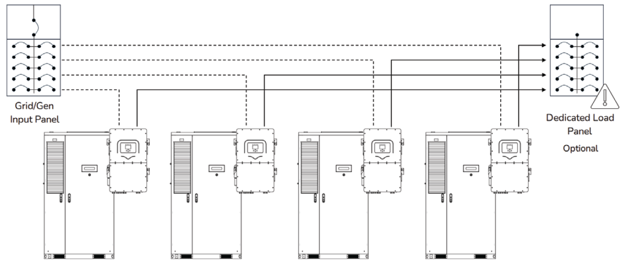
By paralleling the Sol-Ark 30K/60K-3P on the AC bus, you can design system configurations with up to 10 inverters and a total output of 300/600 kW. AC Inputs are paralleled on a common AC input (grid/gen) bus. The same applies to AC outputs on a load bus. Batteries feed the Sol-Ark 30K/60K-3P inverters independently.
The scalability described in this document refers to inverter system-level scalability achieved by paralleling multiple inverters on the AC bus. In this configuration, each inverter operates independently with its dedicated battery connection, while the combined AC output of the inverters is synchronized on the AC bus to meet large power demands. This approach promotes balanced load sharing across all inverters.
Parallel Multiple Sol-Ark 60K-3P on the AC Bus (up to 10 inverters)
NOTE |
|---|
For instructions on paralleling multiple units, refer to the Sol-Ark C&I Installation Guide and User Manual for the corresponding inverter model. |
Systems can be configured with either one battery per inverter or two batteries sharing a single inverter. In all cases, the battery remains within specification. Final system sizing should align with the site’s load profile and desired runtime to ensure optimal performance and value.
NOTICE |
|---|
EQUIPMENT DAMAGE Connect the Sol-Ark inverter’s BMS1 and BMS2 ports only to the CAN port on the LYNK II Gateway using a standard CAT5e or higher cable. Do not connect the inverter's BMS ports directly to the J3 or J4 ports on the AES Cabinet’s High Voltage Box, as this can damage the inverter. Failure to follow these instructions may result in equipment damage. |