
Communication Wiring
To enable both closed-loop inverter communication and cloud-based monitoring, the LYNK II Gateway must be connected to:
The inverter’s BMS port (for real-time battery data exchange)
An active Internet connection through its Ethernet port (optional, for LYNK Cloud access)
Run two CAT6 or higher cables to the cabinet to support both functions.
Connection Type | Wire Size | Max Distance |
|---|---|---|
Communication (CAN) | 16 – 22 AWG | Up to 30 m (100 ft) using 24 AWG |
Ethernet (LAN) | CAT6 or higher | 30 – 120 m (100 – 400 ft) using 23 AWG |
Cable Requirements
Recommended Cable: Use shielded CAT6 or higher to minimize EMI and ensure reliable data transmission.
RJ45 Pinout: Confirm pin assignments match the inverter’s CAN communication spec.
Installation
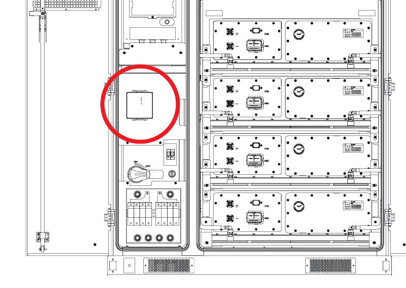
Install the LYNK II Gateway into the AES Cabinet, onto the top shield of the High Voltage Box.
In the location reserved for the LYNK II Gateway, unscrew the nuts from the 4 studs.
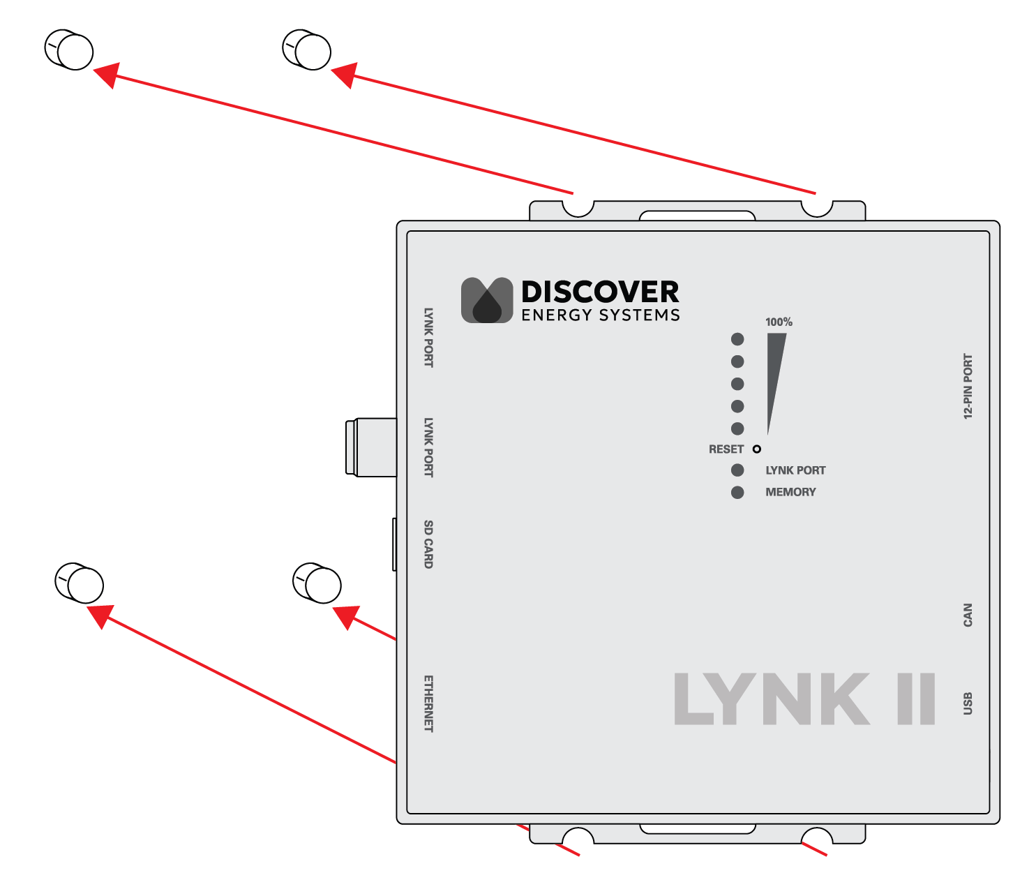
Mount the LYNK II onto the studs and screw on the nuts.
After the LYNK II is mounted, connect the CAT6 cable located nearby to the LYNK port on the LYNK II Gateway. The other end of the CAT6 cable is connected to the J3/J4 port on the High Voltage Box.
NOTICE |
|---|
EQUIPMENT DAMAGE
Failure to follow these instructions may result in equipment damage. |
Inverter Connection: Connect a CAT6 or higher cable between the LYNK II CAN port and the inverter’s BMS port.
(Optional) Internet Access: For your system to use LYNK Cloud, connect a CAT6 or higher cable from the LYNK II Gateway’s Ethernet port to a live internet source.
This setup enables remote monitoring via LYNK Cloud.
LYNK II Gateway Configuration
Launch LYNK ACCESS 2.5.0 or later and update the LYNK II firmware to version 2.5.0 or later.
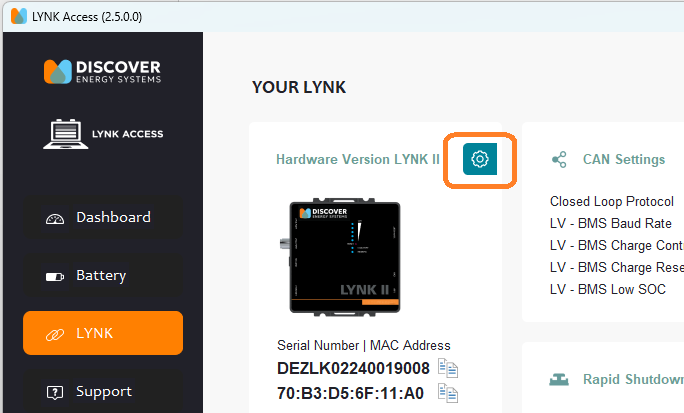
Configure closed-loop communication on LYNK ACCESS.
In the LYNK tile, click on the blue gear icon.
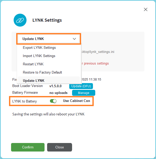
In the LYNK Settings dialog box that appears, from the drop-down menu, select Update LYNK.
In the CAN Settings tile, set the Closed Loop Protocol to HV - BMS.
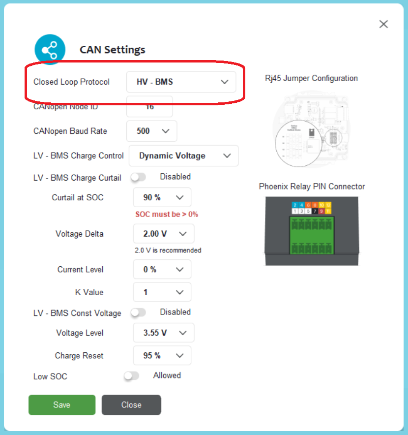
The default setting will work for most installations. Please reach out to Discover if you are looking to change the default settings.
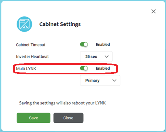
When connecting two inverters to one battery cabinet, two LYNK II Gateways are required. Configure the Cabinet Settings in both LYNK II Gateways to use the Multi LYNK feature.
One Cabinet, One Inverter
Connect the LYNK II Gateway's CAN port to the inverter’s BMS1 or BMS2 port. Connect the LYNK II Gateway’s LYNK Port to the J3 or J4 port on the battery cabinet’s High-Voltage Box.
One Cabinet, Two Inverters
Each inverter requires a LYNK II Gateway. Connect a BMS port on each inverter to establish a communication interface through the LYNK II Gateway with the AES Cabinet for independent communication.
Connect each LYNK II Gateway's LYNK port to the J3 and J4 ports on the battery cabinet’s High Voltage Box. J3 and J4 are internally paralleled, so it doesn’t matter which LYNK II connects to which port on the battery, as long as each gateway has a dedicated connection.
To attach the second LYNK inside the cabinet just left of the other LYNK II, you could use double-sided mounting tape or industrial Velcro.
Two Cabinets, One Inverter
Each battery cabinet requires a LYNK II Gateway. Connect the CAN Out port of the LYNK II Gateways to the BMS1 and BMS2 ports of the inverter. Then, connect each LYNK II’s LYNK Port to either the J3 or J4 port on each battery’s high-voltage box.