Two Inverter, One AES 210HV
|
|---|
ELECTRIC SHOCK AND FIRE HAZARD Failure to follow these instructions may result in death or serious injury. |
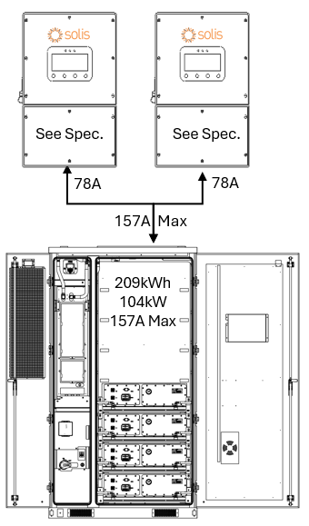
When paired with two Solis S6-EH3P inverters, the AES 210HV cabinet could constrain the inverters to a max 104 kW continuous output limit (only applicable for the S6-EH3P 50-60kW Models). Actual discharge performance depends on the inverter model’s battery-side power capacity, as shown below:
Inverter Model | Battery Discharge Limit | Estimated Runtime (209 kWh usable) |
|---|---|---|
S6-EH3P30K03 | 33 kW (2x66kW) | ~3.16 hours |
S6-EH3P60K04 | 60 kW (2x10⁴kW) | ~2.0 hours |
These runtime estimates assume continuous full-power discharge and operation within safe continuous discharge parameters. Final performance should match the site's energy demand and load profile.
System Scalability – Two Inverters, One AES 210HV
Two of the Solis S6-EH3P inverters are paired with one AES 210HV battery cabinet. This setup supports:
209 kWh of usable backup energy between two inverters
Discharge power is limited by the total inverter capacity or battery power limitation (max 104 kW)
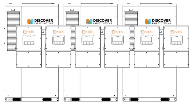
Up to six inverters can be connected in parallel on the backup side, providing up to 360 kW of continuous backup power and approximately 636 kWh of total backup energy (3 × 209 kWh).
Grid-Tied (Non-Backup) Scalability
The number of inverters or batteries is not limited for non-backup use. Each inverter runs independently, allowing systems to scale as large as needed for energy shifting, peak shaving, or other grid-interactive applications.
DC Battery Wiring – One Inverter, One AES 210HV
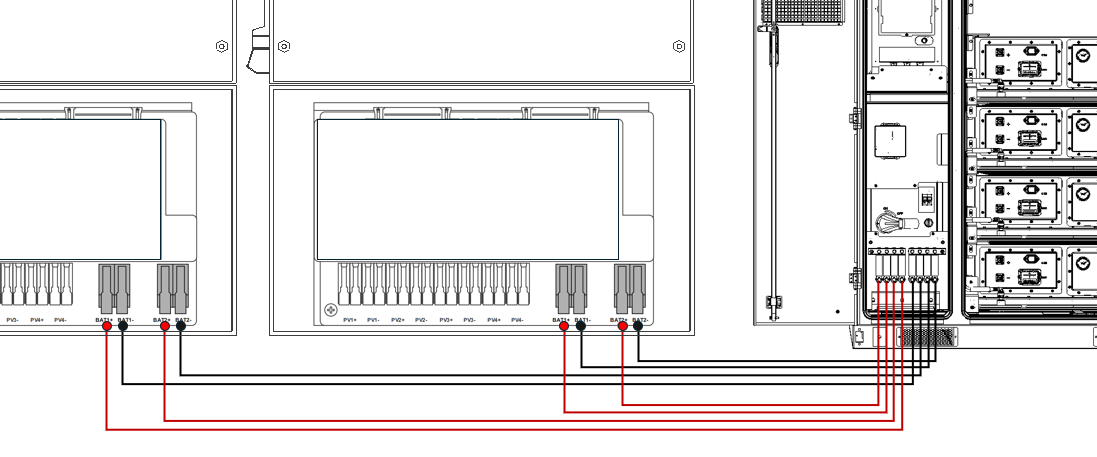
Each Solis S6-EH3P inverter has two battery input terminals, each rated up to 70 A. The AES 210HV connects using:
Two positive and two negative #4 AWG conductors to each inverter.
Each conductor is protected by a 70 A fuse in the AES 210HV cabinet’s built-in DC distribution box.
This setup ensures balanced current flow to each inverter’s internal DC/DC converter and supports up to 60 kW continuous charge/discharge depending on the inverter model.
Communication – Two Inverter, One AES 210HV
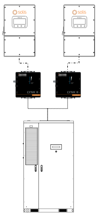
In a two-to-one configuration, separate LYNK II Gateways are required for each inverter to enable real-time, closed-loop control. The AES 210HV communicates with the Solis inverter through the LYNK II Gateway included with the AES 210HV system, plus a second LYNK II Gateway (the second LYNK II Gateway is a separate purchase).
Use a standard CAT5 or CAT6 Ethernet cable, wired straight-through with RJ45 plugs on both ends.
Connect one end to the Solis inverter's BMS1 port
Connect the other end to the CAN port on the LYNK II Gateway
This communication link allows the inverter to receive live battery data—including state of charge, voltage, current, temperature, and charge/discharge limits—ensuring safe, accurate, and optimized operation.