
Parallel Battery Installation Procedure (Parallel Wiring Kit)
The following instructions identify how to connect batteries and inverters in parallel using the HELIOS ESS Parallel Wire Kit (950-0068). One kit is required to parallel two batteries. Two kits are required to parallel three batteries.
|
|---|
ELECTRIC SHOCK AND FIRE HAZARD
Failure to follow these instructions may result in injury. |
NOTICE |
|---|
UNBALANCED BATTERY CELLS Paralleling more than three batteries using the Parallel Wiring Kit may lead to unbalanced battery cells. Failure to follow these instructions may result in equipment damage. |
Install equipment following the standards set by the local authority having jurisdiction.
Prepare the inverter and battery for wiring.
If the inverter is wired to a power source, open the disconnect and set the inverter OFF.
Use a DMM or other voltage measuring device to confirm the circuit is de-energized.
If the circuit in which the battery is installed has a disconnect, open the disconnect to isolate the battery.
Set both the battery BMS and the breaker to the OFF position.
Use a DMM or other voltage measuring device to confirm the circuit is de-energized.
Wire the inverter.
The Battery to Inverter Power Cables 2/0 AWG (950-0070) or 1/0 AWG (950-0071) are available to wire the batteries to the inverter. Select the cable set compatible with your inverter and inverter settings.
NOTE |
|---|
|
Ensure the cable connections are clean and in working order.
Connect the positive battery cable to a positive battery terminal on the inverter.
Connect the negative battery cable to a negative terminal on the inverter.
When using ONE Set of Battery to Inverter cables
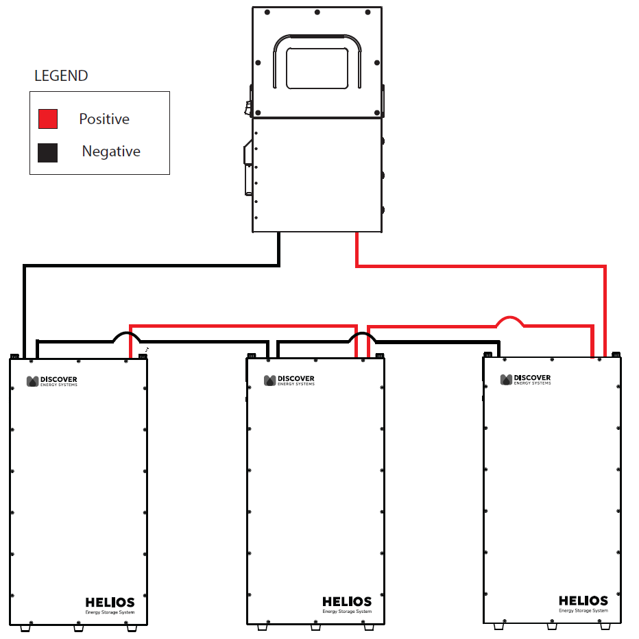
Three Batteries in Parallel (Two Parallel Wire Kits 950-0068)
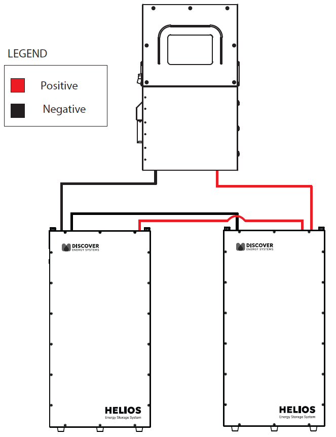
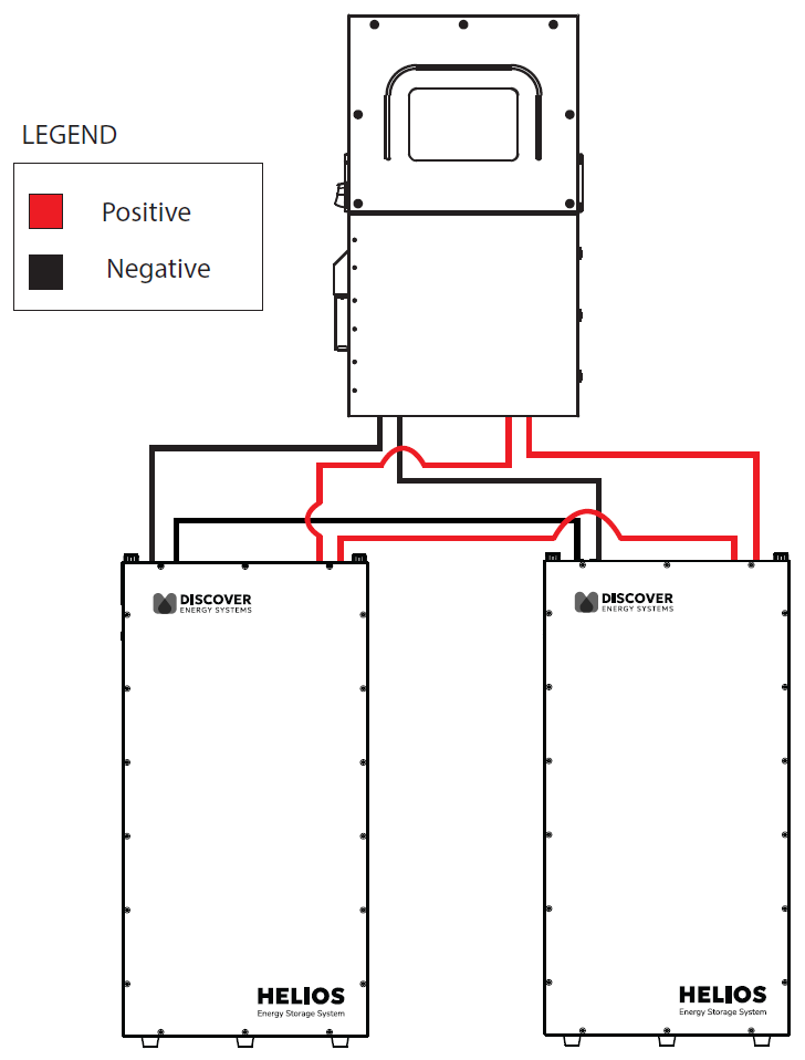
Two Batteries in Parallel (One Parallel Wire Kit 950-0068)
Connect the positive (+) battery cable in the HELIOS ESS Parallel Wire Kit (950-0068) to a receiving pin of the positive battery terminals on a battery at one end of the battery bank. Push the ends of cables against the receiving pins to secure the connection.
Connect Cables to Battery Terminals
Connect the negative (-) battery cable to a receiving pin of the negative battery terminals on the battery at the other end of the battery bank. Push the ends of cables against the receiving pins to secure the connection.
Connect the positive (+) and negative (-) battery cables in the HELIOS ESS Parallel Wire Kit (950-0068) to the receiving pins of the positive and negative battery terminals on batteries as shown in the diagrams. Push the ends of cables against the receiving pins to secure the connection.
When Using TWO Sets of Battery to Inverter Cables
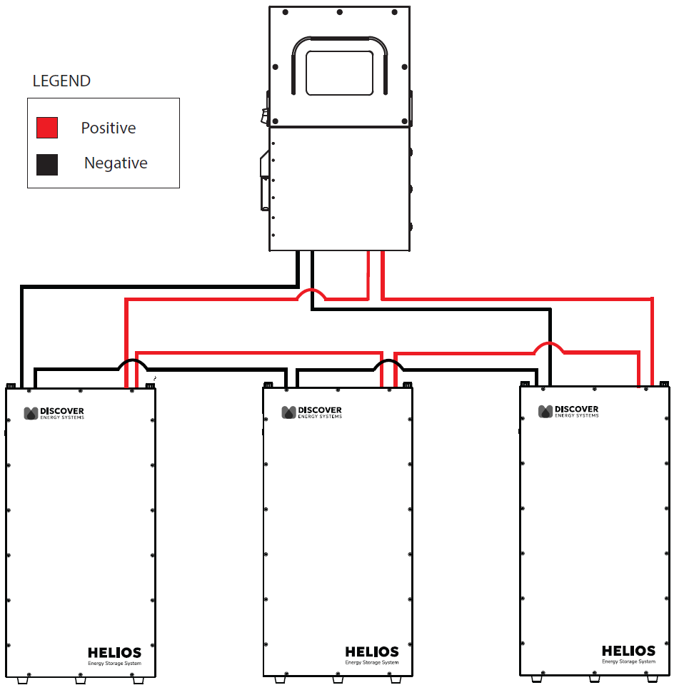
Three Batteries in Parallel (Two Parallel Wire Kits 950-0068)
Two Batteries in Parallel (One Parallel Wire Kit 950-0068)
Connect one of the positive battery cables from the inverter to a battery on one end of the battery bank, and connect the other cable to the battery on the other end of the battery bank. Push the ends of cables against the receiving pins to secure the connection. Refer to the “Terminal Connections and Hardware” section.
Connect Cables to Battery Terminals
Connect one of the negative battery cables from the inverter to a battery on one end of the battery bank, and connect the other cable to the battery on the other end of the battery bank. Push the ends of cables against the receiving pins to secure the connection.
Connect the positive (+) and negative (-) battery cables in the HELIOS ESS Parallel Wire Kit (950-0068) to the receiving pins of the positive and negative battery terminals on batteries as shown in the diagrams. Push the ends of cables against the receiving pins to secure the connection.
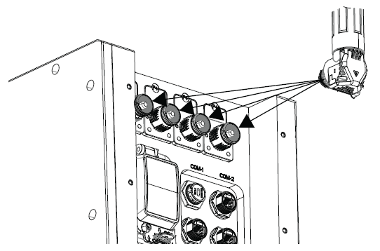
Connect the CAN communication cables.
Set all battery BMS to ON (ON/OFF key).
Energize the system by setting all battery breakers to ON (close).
Close the circuit disconnect if it is open.
NOTICE |
|---|
TERMINAL BURNOUT Failure to securely lock the ends of battery cables to the receiving pins on the battery will increase resistance and lower voltage, leading to burnout of the terminals and voiding of the warranty. Failure to follow these instructions may result in equipment damage. |
NOTE |
|---|
|