
|
|
|---|
|
ELECTRIC SHOCK AND FIRE HAZARD
Failure to follow these instructions may result in death or serious injury. |
CAB-106, CAB-160, and CAB-210 Configurations
When two AES Cabinets are paired with a single Solis S6-EH3P inverter, the AES Cabinet’s maximum continuous current limit is 157 A, operating within its rated 209 / 314 / 418 kWh continuous output limit. Actual discharge performance depends on the inverter model’s battery-side power capacity, as shown below.
Full Load Duration
|
Inverter Model |
Battery Discharge Limit |
CAB-106 |
CAB-160 |
CAB-210 |
|---|---|---|---|---|
|
AC Output / Usable Storage / Estimated Runtime |
||||
|
S6-EH3P29.9K |
29.9 kW |
29.9 kW / 208 kWh / 7 hours |
29.9 kW / 314 kWh / 10½ hours |
29.9 kW / 418 kWh / 13½ hours |
|
S6-EH3P30K |
30 kW |
30 kW / 208 kWh / 7 hours |
30 kW / 314 kWh / 10½ hours |
30 kW / 418 kWh / 13½ hours |
|
S6-EH3P40K |
40 kW |
40 kW / 208 kWh / 5 hours |
40 kW / 314 kWh / 7½ hours |
40 kW / 418 kWh / 10½ hours |
|
S6-EH3P50K |
50 kW |
50 kW / 208 kWh / 4 hours |
50 kW / 314 kWh / 6 hours |
50 kW / 418 kWh / 8 hours |
* Curtailed by the battery.
These autonomy estimates assume continuous full-power discharge and operation within safe continuous discharge parameters. Final performance should match the site's energy demand and load profile.
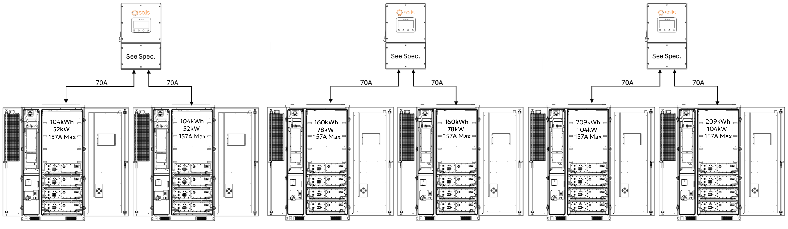
System Scalability – One Inverter, Two AES Cabinets
Each Solis S6-EH3P inverter can be paired with two AES battery cabinets, doubling the usable energy per inverter while maintaining discharge power based on inverter size.
In this setup:
-
209 / 314 / 418 kWh of usable backup energy per inverter (2 × 10⁴ kWh / 2 × 157 kWh / 2 × 209 kWh)
-
Discharge power limited by the inverter model (29.9–50 kW)
-
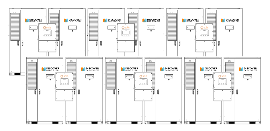
Up to ten inverters can be connected in parallel on the backup side, supporting 299-500 kW of backup power and approximately 2.09–4.18 MWh of total backup energy (10 × 209 kWh / 10 × 314 kWh / 10 × 418 kWh).
Grid-Tied (Non-Backup) Scalability
The number of inverters or batteries is unlimited for non-backup use. Each inverter runs independently, allowing systems to scale as large as needed for energy shifting, peak shaving, or other grid-interactive applications.
DC Battery Wiring – One Inverter, Two AES Cabinets
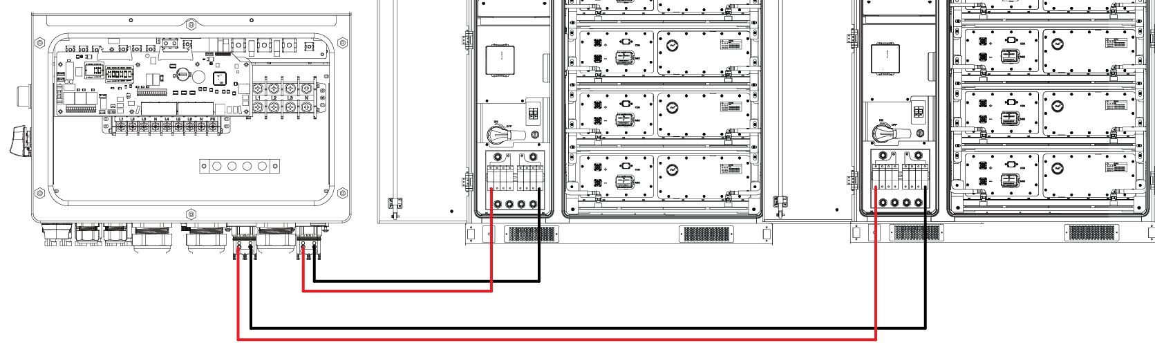
When connecting two AES battery cabinets to a single Solis S6-EH3P inverter, each cabinet is wired to a dedicated battery input terminal on the Solis inverter:
-
Battery 1 connects to the inverter’s BAT1 terminals
-
Battery 2 connects to the inverter’s BAT2 terminals
The inverter’s integrated dual DC/DC converters are independently fused and control each input, allowing the inverter to manage each battery cabinet separately while balancing charge and discharge as needed.
Always follow AS/NZS 3000 Wiring Rules and the local authority having jurisdiction for conductor sizing, 1,000 Vdc insulation rating, and proper torque values. Verify polarity before energising the system.
Communication – One Inverter, Two AES Cabinets
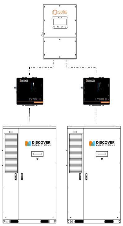
Each AES battery cabinet uses its own LYNK II Gateway for managed (closed-loop) communication with the Solis inverter in a two-to-one configuration. The inverter’s two BMS ports (BMS1 and BMS2) allow it to communicate with each battery independently.
-
Use standard CAT6 or higher Ethernet cables, wired in a straight-through configuration with RJ45 plugs on both ends.
-
Connect one cable from LYNK II #1 CAN port to the Solis inverter’s BMS1 port. Connect another cable to LYNK II #1’s LYNK port to the J3/J4 port on the AES Cabinet’s High Voltage Box. On most AES Cabinets, a CAT6 cable is already connected to the J3 port on the AES Cabinet’s High Voltage Box and is accessible from the LYNK II.
-
Connect a third cable from LYNK II #2 CAN port to the Solis inverter’s BMS2 port. Connect a fourth cable from LYNK II #2’s LYNK port to the J3/J4 port on the AES Cabinet’s High Voltage Box.
This setup enables the inverter to independently manage and monitor both battery cabinets, receiving real-time data for state of charge, voltage, current, temperature, and charge/discharge limits from each LYNK II Gateway. Two independent LYNK II Gateways ensure precise, safe, and optimized performance across both battery units.