
One Inverter, Two AES Cabinet
|
|---|
ELECTRIC SHOCK AND FIRE HAZARD Failure to follow these instructions may result in death or serious injury. |
CAB-106, CAB-160, and CAB-210 Configurations
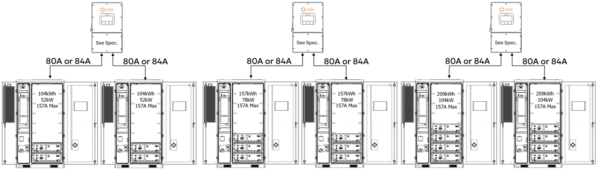
When two AES Cabinets are paired with a single Solis S6-EH3P inverter, the AES Cabinets’ maximum continuous current limit is 157 A, operating within their rated 104 / 156 / 208 kW continuous output limit. Actual discharge performance depends on the inverter model’s battery-side power capacity, as shown below.
Full Load Duration (Operation at Max Power)
Inverter Model | Inverter Battery Discharge Limit | 2 × CAB-106 | 2 × CAB-160 | 2 × CAB-210 |
|---|---|---|---|---|
AC Output / Usable Storage / Estimated Runtime | ||||
S6-EH3P30K03 | 30 kW | 30 kW / 208 kWh / 7 hours | 30 kW / 314 kWh / 10½ hours | 30 kW / 418 kWh / 13½ hours |
S6-EH3P40K04 | 40 kW | 40 kW / 208 kWh / 5 hours | 40 kW / 314 kWh / 7½ hours | 40 kW / 418 kWh / 10½ hours |
S6-EH3P50K04 | 50 kW | 50 kW / 208 kWh / 4 hours | 50 kW / 314 kWh / 6 hours | 50 kW / 418 kWh / 8 hours |
S6-EH3P60K04 | 60 kW | 60 kW / 208 kWh / 3½ hours | 60 kW / 314 kWh / 5 hours | 60 kW / 418 kWh / 7 hours |
These run times assume continuous full-power discharge at the inverter's rated limit. While the inverter determines the maximum power output, the dual-cabinet setup extends runtime. Dual cabinets increase total stored energy and are ideal for longer-duration backup or deeper cycling in time-of-use and peak-shaving applications.
System Scalability – One Inverter, Two AES Cabinets
Each Solis S6-EH3P inverter can be paired with two AES battery cabinets, doubling the usable energy per inverter while maintaining discharge power based on inverter size.
In this setup:
208 / 314 / 418 kWh of usable backup energy per inverter (2 × 10⁴ kWh / 2 × 157 kWh / 2 × 209 kWh)
Discharge power limited by the inverter model (30–60 kW)
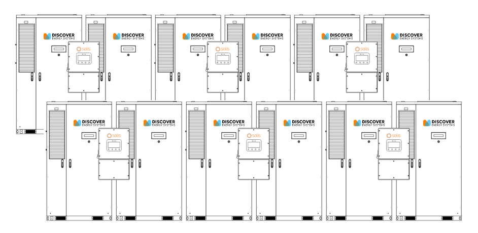
Up to ten inverters can be connected in parallel on the backup side, supporting 300-600 kW of backup power and approximately 2.08–4.18 mWh of total backup energy (10 × 208 kWh / 10 × 314 kWh / 10 × 418 kWh).
Grid-Tied (Non-Backup) Scalability
For grid-tied applications, the number of batteries or inverters is not limited. Each inverter operates independently, enabling large-scale deployments for energy arbitrage, load shifting, or demand charge reduction without backup power constraints.
DC Battery Wiring – One Inverter, Two AES Cabinets
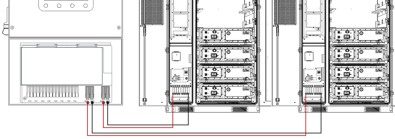
When connecting two AES battery cabinets to a single Solis S6-EH3P inverter, each cabinet is wired to a dedicated battery input terminal:
Battery 1 connects to the inverter’s BAT1 terminals
Battery 2 connects to the inverter’s BAT2 terminals
The inverter’s integrated dual DC/DC converters are independently fused and control each input, allowing the inverter to manage each battery cabinet separately while balancing charge and discharge as needed.
Always follow NEC guidelines for conductor sizing, 1,000 Vdc insulation rating, proper torque values, and verify polarity before energizing the system.
Communication – One Inverter, Two AES Cabinets
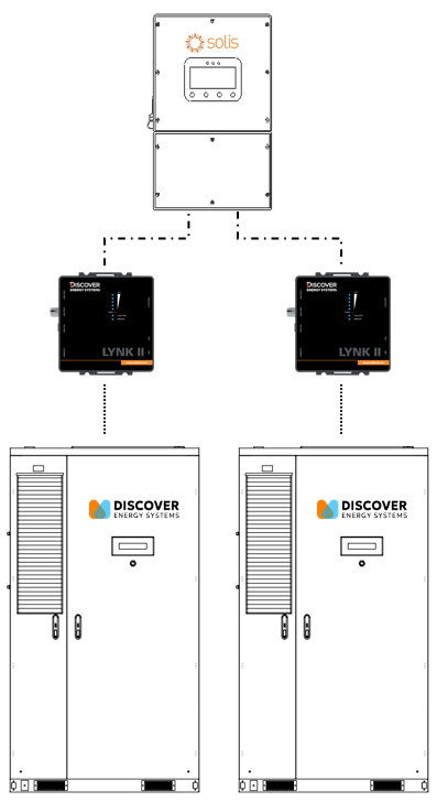
Each AES battery cabinet uses its own LYNK II Gateway for closed-loop communication with the Solis inverter in a two-to-one configuration. The inverter’s two BMS ports (BMS1 and BMS2) allow it to communicate with each battery independently.
Use standard CAT6 or higher Ethernet cables, wired in a straight-through configuration with RJ45 plugs on both ends.
Connect one cable from LYNK II #1 CAN port to the Solis inverter’s BMS1 port. Connect another cable to LYNK II #1’s LYNK port to the J3/J4 port on the AES Cabinet’s High Voltage Box. On most AES Cabinets, a CAT6 cable is already connected to the J3 port on the AES Cabinet’s High Voltage Box and is accessible from the LYNK II.
Connect a third cable from LYNK II #2 CAN port to the Solis inverter’s BMS2 port. Connect a fourth cable from LYNK II #2’s LYNK port to the J3/J4 port on the AES Cabinet’s High Voltage Box.
This setup enables the inverter to independently manage and monitor both battery cabinets, receiving real-time data for state of charge, voltage, current, temperature, and charge/discharge limits from each LYNK II Gateway. Two independent LYNK II Gateways ensure precise, safe, and optimized performance across both battery units.