
Cabinet Wiring Connections
NOTICE |
|---|
DAMAGE DUE TO WATER AND DUST INGRESS
Failure to follow these instructions may result in equipment damage. |
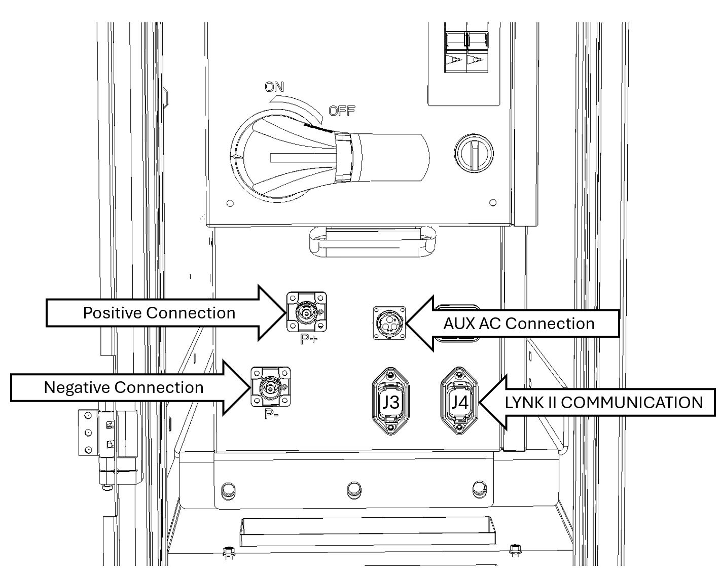
HV Box Connection Points
Connecting Communications to LYNK Gateway
Plug the LYNK II communication cable into either the J3 or J4 port on the HVB. Route and connect the communication cable (RJ45) to the LYNK Port on the LYNK II Communication Gateway.
NOTICE |
|---|
COMMUNICATION NETWORK DAMAGE
Failure to follow this instruction may result in equipment damage. |
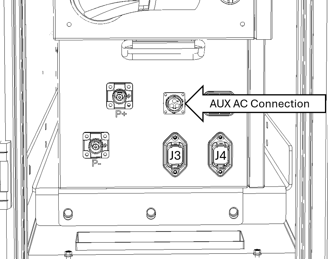
AUX AC Input Connection
AC Wiring to AUX AC Port
Terminate the AC input wiring from a 200-275VAC source (e.g., transformer or other AC power supply) to the AUX AC Wiring Assembly. Plug the AUX AC Wiring Assembly into the AUX AC connection port on the HVB.
|
|---|
ELECTRIC SHOCK AND FIRE HAZARD
Failure to follow these instructions may result in injury. |
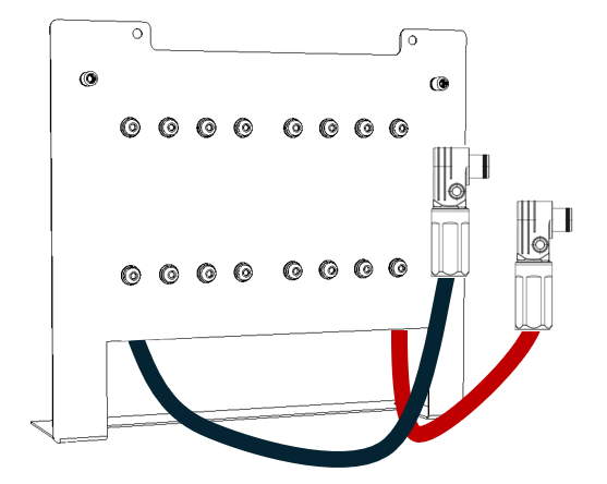
DC Distribution Connection to HV Box
High-Current Conductors to DC Distribution Panel
Plug the corresponding ends of the high-current positive and negative conductors into their respective ports on the High-Voltage Box (P+ & P-). Red/Orange to P+ and black to P-.
DC Wiring to HV Box
Mount the DC Distribution Panel and secure the high-current positive and negative conductors to the corresponding busbar on the DC Distribution panel.
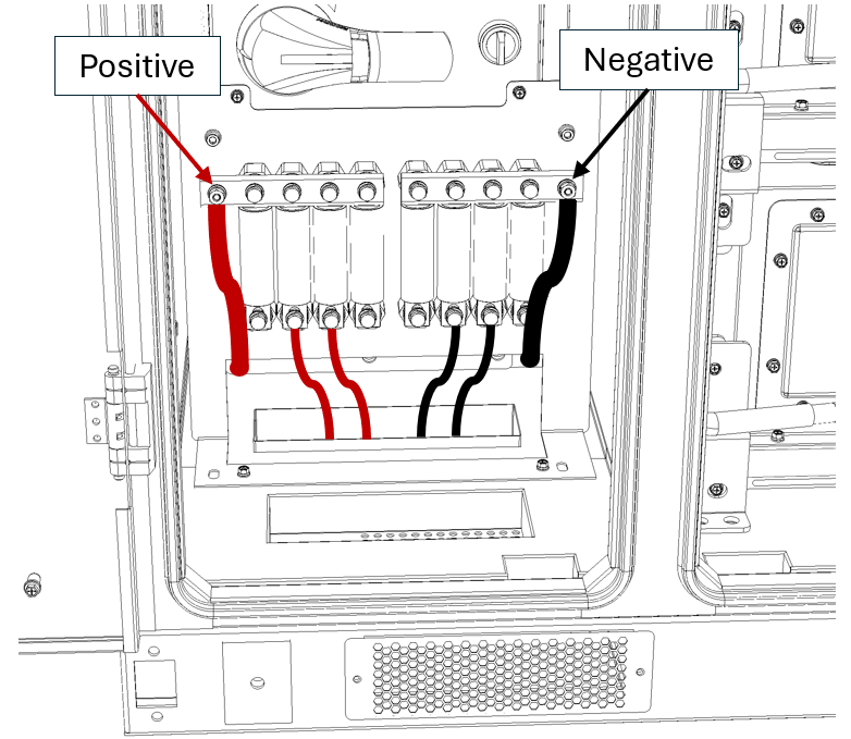
DC Distribution Connections
Terminate Inverter DC Conductors
Route DC Conductors: Run the inverter's DC conductors to the fuse terminals.
Crimp & Secure: Attach an appropriate ring terminal to each conductor and securely fasten them to the fuse. Leaving sufficient slack to prevent strain.
Polarity Check: Verify that all connections from the HVB (High-Voltage Battery) to the DC Distribution Panel and from the DC Distribution Panel to the Inverter are properly terminated with the correct polarity.
Install the DC Distribution Panel cover securely before powering on the system.
NOTICE |
|---|
REVERSE POLARITY DAMAGE Incorrect polarity can cause high-current faults or damage to system components. Failure to follow these instructions may result in equipment damage. |