
Thermal Management System (TMS)
AES 210HV Thermal Management System Overview
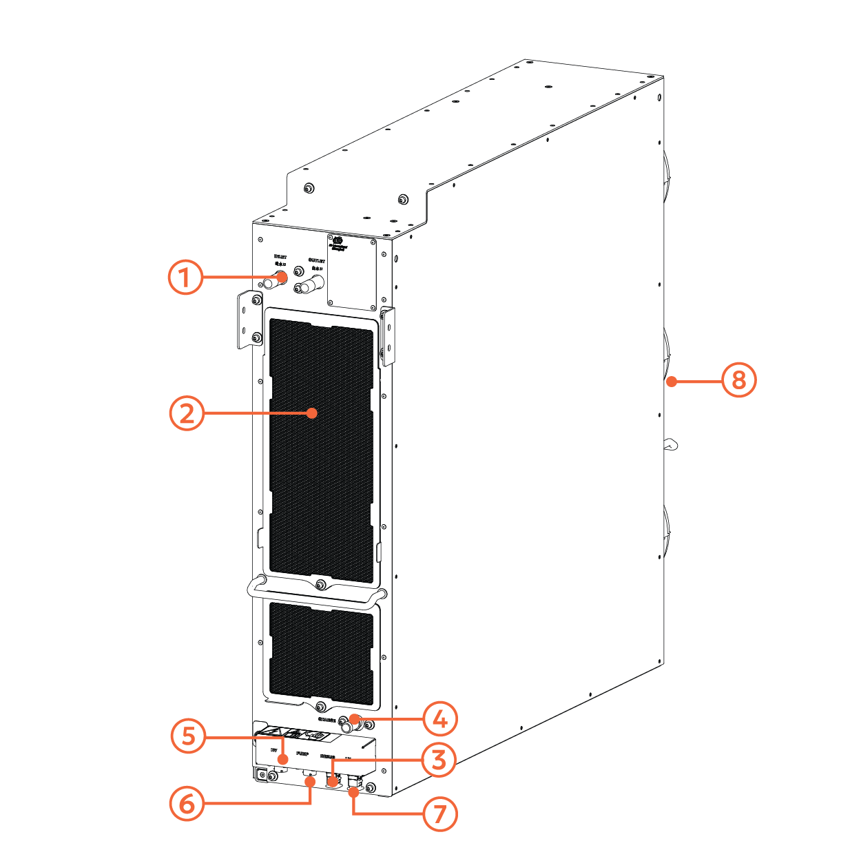
No. | Name | Description |
|---|---|---|
1 | Inlet / Outlet | Connects to the cooling system for liquid coolant circulation through the TMS system. |
2 | Air Intake | Facilitates air intake for the cooling mechanism of the TMS. |
3 | Debug/Service Port | Used for diagnostics, testing, and software updates. |
4 | Charge Pipe | Allows for refilling coolant into the system. |
5 | AC Input | Provides AC power to the TMS. |
6 | Pump DC Power Input | Supplies power to the liquid coolant pump during maintenance or service operations. |
7 | Proprietary Communication Port | Connects the TMS to other internal systems. |
8 | Air Exit | Supports ventilation and heat dissipation by facilitating air exhaust using three fans. |
The AES 210HV features a liquid-based Thermal Management System (TMS) designed to maintain optimal operating conditions for the battery packs. The TMS provides both heating and cooling, allowing the batteries to function efficiently across a wide ambient temperature range.
The system circulates a 50/50 glycol mixture in a closed-loop circuit to regulate battery temperature.
The TMS operates under slight positive pressure to ensure proper coolant flow.
If the system loses pressure due to a leak, a low-pressure alarm will trigger, automatically shutting down the TMS until the issue is resolved and servicing is completed.
Cooling Mode
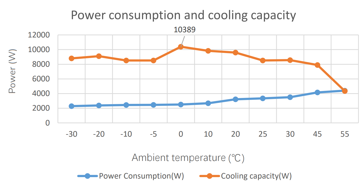
Cooling Power Consumption
When battery temperatures exceed the preset threshold, the Thermal Management System (TMS) initiates the cooling cycle. Liquid coolant flows through the battery pack’s cooling plates, absorbing excess heat before being directed to an evaporator. There, heat is transferred to a refrigerant, rapidly cooling the fluid before it recirculates through the system. Three high-efficiency fans at the rear of the TMS expel the extracted heat from the cabinet, ensuring effective thermal regulation and preventing overheating.
Cooling activates when the system-wide temperature reaches ≥ 30°C or any battery pack exceeds 32°C and stops when both the system average drops to ≤ 28°C and all individual packs fall below 30°C. Upon activation, the TMS starts the coolant pump within 20 seconds and engages the compressor after 30 seconds, adjusting power dynamically to maintain a target coolant temperature of 20°C ±1°C. Cooling takes priority over other functions unless heating is simultaneously required, in which case the system enters self-circulation mode.
Heating Mode
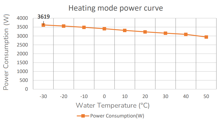
Heating Power Consumption
When the battery temperature drops below a predefined threshold, especially in cold environments, the Thermal Management System (TMS) activates a heating cycle. The system circulates coolant through a PTC heater, warming it before directing it to the battery packs. This process continues until the battery temperature reaches the optimal operating range, ensuring stable performance and longevity while preventing cold-related efficiency losses.
Heating activates during discharge if the system-wide temperature is ≤ -5°C or any battery pack reaches ≤ -10°C, and during charging if the system-wide temperature is ≤ 10°C or any pack is ≤ 5°C. Heating turns off when the system-wide temperature reaches ≥ 25°C and all individual packs are at least 20°C, ensuring uniform thermal conditions. The TMS controls PTC heaters, maintaining a target coolant temperature of 30°C, and limits charging/discharging until safe operating temperatures are restored.