
High Voltage Box (HV Box)
High Voltage Box
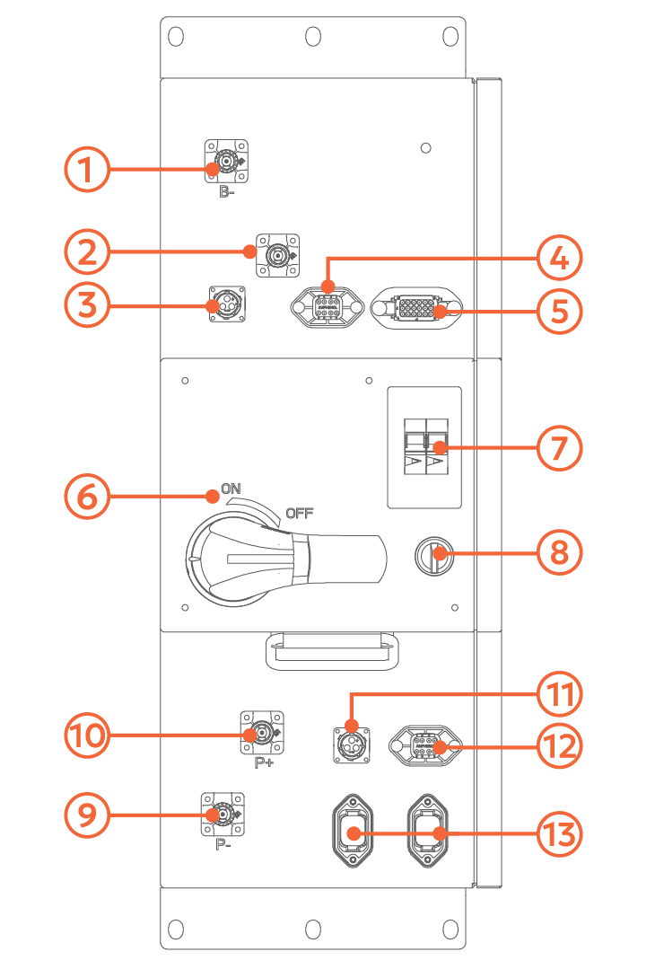
No. | Name | Description |
|---|---|---|
1 | B- | Battery Pack Negative (-) Input |
2 | B+ | Battery Pack Positive (+) Input |
3 | J7 | AC Auxiliary Supply to Thermal Management Unit |
4 | J1 | Thermal Management Communication Port |
5 | J2 | Inter-battery Communication Port for the First Battery Pack |
6 | DC Disconnect | Dual Pole DC Disconnect for the Battery Output (P+/P-) |
7 | AC Auxiliary Power Breakers | Breakers/Disconnects for Cabinet Power Circuits (Main, BMS, Thermal Management) |
8 | UPS Switch | Switch for the Uninterruptible Power Supply (UPS), which provides backup power for a black start scenario. |
9 | P- | Inverter Negative (-) Output |
10 | P+ | Inverter Positive (+) Output |
11 | J6 | AC Input (Single phase 240 Vac, 60 Hz) |
12 | J5 | Proprietary Communication Port |
13 | J3/J4 | LYNK II Communication Ports |
NOTE |
|---|
|