
Relay Hardware Installation
NOTICE |
|---|
HAZARD OF EQUIPMENT DAMAGE Protect the relay contacts from overcurrent conditions with an external fuse. Failure to follow these instructions may result in equipment damage. |
NOTE |
|---|
For examples of how to use the relays, refer to the Appendix, Example Relay Configurations. |
See the 12-pin Connector Layout table and image below for the locations of pins on the Phoenix connector. Insert the connector wire into the correct pin hole. From the top of the connector pin hole, use a jeweler's flathead screwdriver to compress the screw and secure the wire. Refer to Configuring Relays with LYNK ACCESS for instructions on configuring the relays. The LYNK II relays are disabled by default.
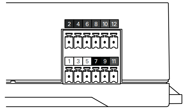
12-Pin Connector Layout | |||||
|---|---|---|---|---|---|
2 | 4 | 6 | 8 | 10 | 12 |
RELAY 3 COM | RELAY 3 N/O | RELAY 2 N/O | RELAY 2 COM | RELAY 1 N/O | RELAY 1 COM |
1 | 3 | 5 | 7 | 9 | 11 |
CAN HIGH | CAN LOW | CAN GND | POWER GND | POWER Vin (13-90V) | RELAY 1 N/C |
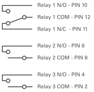
Relay | Output Characteristics |
|---|---|
Relay 1 | N/O 0-30 Vdc, maximum 5 A N/O 0-250 Vdc, maximum 5 A N/O 0-30 Vdc, maximum 5 A N/O 0-250 Vdc, maximum 5 A |
Relay 2 | N/O 0-30 Vdc, maximum 5 A N/O 0-250 Vdc, maximum 5 A |
Relay 3 | N/O 0-30 Vdc, maximum 5 A N/O 0-250 Vdc, maximum 5 A |
NOTE |
|---|
The top and bottom Phoenix connectors can be removed by pulling them out of their socket. Reinstall in the same socket |