
Setting Closed-loop Configuration on the Morningstar Device
Commissioning the GenStar MPPT
The following setup prepares the GenStar MPPT for operation or further programming. Initial commissioning, including specifying the battery, is only possible from the meter interface.
Connect the batteries to the GenStar MPPT through the LYNK II and the ReadyBMS Module. Refer to Connect LYNK II to the Morningstar Network.
Switch on the battery to power the MPPT controller.

Meter Interface
The Morningstar logo appears on the controller’s Meter interface and displays the hardware and software versions. Press the arrows to navigate the menus.
Select and confirm the display language.
Next, enable or disable Ethernet Writes to control remote write operations over Ethernet, as required by the application.
Select the System Voltage (12V, 24V, or 48V) to match the batteries used by the application.
Set the UTC Time (Universal Time)
Set the Local Time Offset for the time zone.
With the ReadyBMS module installed on the GenStar MPPT, select Yes for the Closed Loop BMS.
For the BMS Battery Type, select Discover.
Set the Battery Load Profile (low voltage disconnect / reconnect) for the MPPT controller. Set the value in brackets if the application requires a larger contingency reserve on the battery.
12 V / 13.2 V (12.5 / 13.15 V)
24 V / 26.2 V (25 / 26.3 V)
48 V / 52.8 (50 V / 52.6 V)
Consider the self consumption of equipment in the system when setting the Battery Load Profile.
Reboot the MPPT and start using it with the batteries.
NOTE |
|---|
Rebooting the MPPT is required to update the MPPT with the edited settings. |
Setting up from the Meter Interface
After the GenStar MPPT is commissioned, use the meter interface to configure settings that were unavailable during commissioning.
After the MPPT is powered up, touch the down arrow to display the Main Menu.
Press the arrow buttons to navigate the menus.
Main Menu > Setup > Installer Password
Enter the installer password defined in the GenStar Installation, Operation and Maintenance Manual.Main Menu > Installer Setup > Charger > Battery Info > Battery Bank Size > Edit (Hold)
Confirm the size is correctly set as the Rated Capacity (Ah) of the battery times the number of batteries. Change the battery bank size if required.Main Menu > Installer Setup > Charger > Battery Profile > Presets
Set the battery profile if required. While you can now begin using the batteries with the system, further configuration may be required. See “Setting up from the LiveView Web Interface”, below.Apply changes, reboot the MPPT, and use it with the batteries.
NOTE |
|---|
|
Setting up from the LiveView Web Interface
Although the GenStar MPPT cannot be commissioned using LiveView, once commissioned and connect to the network, use LiveView to configure settings from a Web interface.
After the GenStar MPPT is commissioned, powered ON, and connected to the network, connect to the power conversion device by typing GenStar’s IP address into a web browser. (E.g. http://192.168.1.253, find the IP address in Main Menu > SETTINGS > Network)
The LiveView web interface opens.
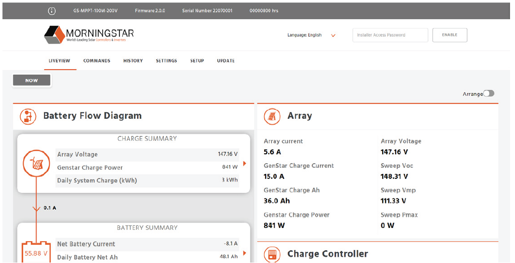
LiveView
In the Installer Access Password field, enter the installer password defined in the GenStar Installation, Operation and Maintenance Manual.
INSTALLER SETUP > Charger > Battery Info > Battery Size
Confirm the size is correctly set as the Rated Capacity (Ah) of the battery times the number of batteries. Change the battery size if required.
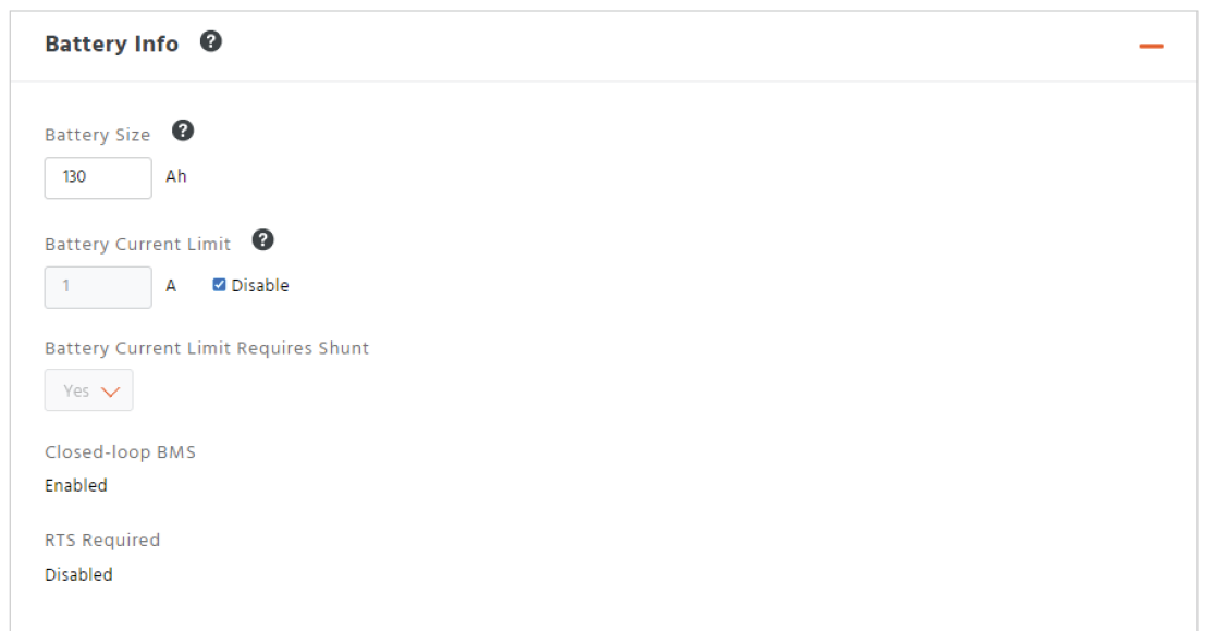
Battery Info
INSTALLER SETUP > Load > Low Voltage Disconnect/Reconnect Profile
Select Custom and Voltage only.
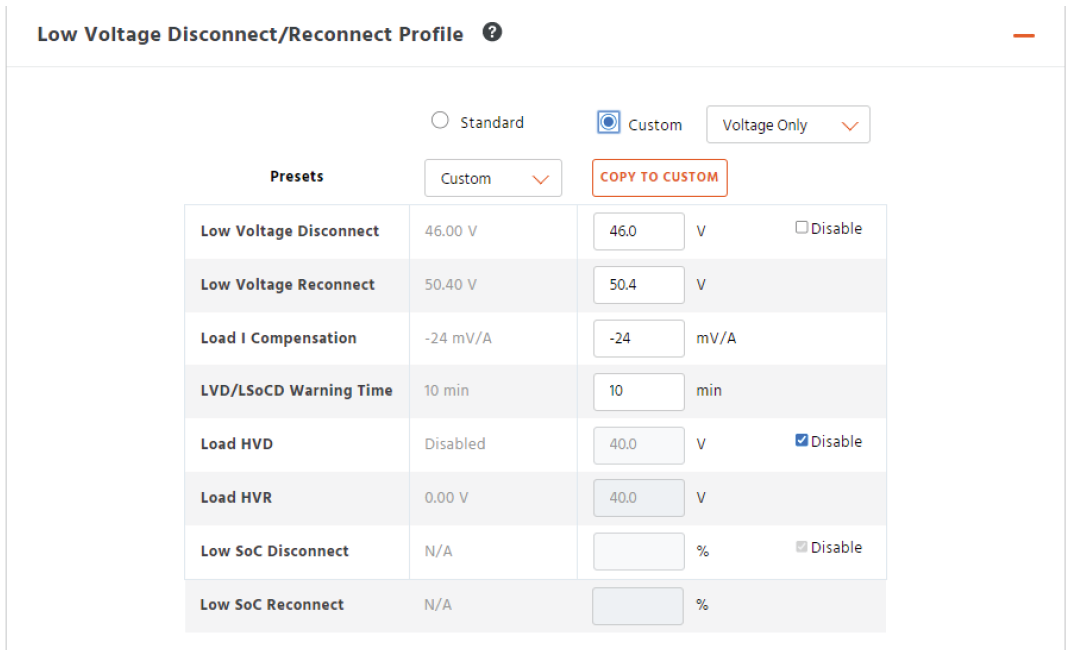
Low Voltage Disconnect/Reconnect Profile
On this page you can set various conditions for disconnecting the batteries from the equipment.
Suggested values are shown in the table below. Set the value in brackets if the application requires a larger contingency reserve.
48V | AES RACKMOUNT 48-48-5120 / 48-48-5120-H | HELIOS ESS 52-48-16000 |
|---|---|---|
Low Voltage Disconnect | 48 V (50 V) | |
Low Voltage Reconnect | 52.8 V (52.6) | |
Load | Compensation | 0 | |
LVD/LSoCD Warning Time | 1 minute | |
INSTALLER SETUP > Charger > SoC LED Transitions
Available for use with a ReadyBMS module, configure the battery SOC values that trigger changes in the LED on the GenStar MPPT. This could be useful for fast troubleshooting of the system.
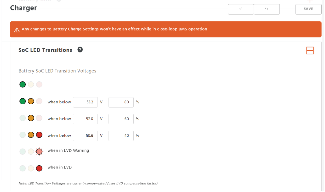
Battery SoC LED Transition Voltages and SoC Percentages
Click the Save button.
Reboot the MPPT and start using it with the batteries.
NOTE |
|---|
Rebooting the MPPT is required to update the MPPT with the edited settings. |
Verifying the Connection
Verify the operation of the batteries and the GenStar MPPT with the Morningstar LiveView web pages.
After the GenStar MPPT is configured, powered ON, and connected to the network, connect to the power conversion device from a computer web browser. (E.g. http://192.168.1.253, find the IP address in Main Menu > SETTINGS > Network)
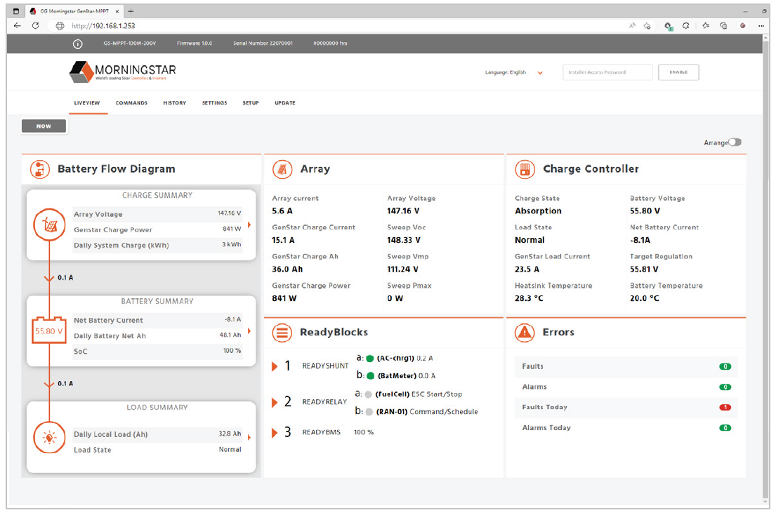
LiveView
In the LIVEVIEW tab, confirm the connected charge controller, battery measurements, and other connected devices.
In the SETTINGS tab, review the settings of the charge controller.
Additionally, look at the State-of-charge LEDs on the MPPT controller and the COM Indication LED on the ReadyBMS module. After the MPPT controller starts, the LEDs should display green or yellow, and the lower LED on the ReadyBMS module should blink green.
If any displays indicate an issue, confirm all the connections (cables and connectors), confirm LYNK II is configured correctly, and confirm the settings on the GenStar MPPT.