
|
NOTICE |
|---|
|
OVERCHARGE / OVERDISCHARGE HAZARD In a closed-loop configuration with the BMS Lithium Batt function enabled, the BMS_Err_Stop parameter must be enabled. If the BMS_Err_Stop parameter function is not enabled, the Sol-Ark inverter will continue to operate based on the last communicated battery values. Depending on the mode of operation at the time of communication fault and given enough time, the Sol-Ark inverter-charger will eventually put the attached battery into an overcharged or fully discharged state. When that occurs, either situation will trigger the Discover Lithium Battery BMS to self-protect and disconnect the battery from the system. Failure to follow these instructions may result in equipment damage. |
|
NOTE |
|---|
|
It is recommended that the Sol-Ark inverter be programmed with the appropriate open-loop settings before enabling closed-loop communication. |
Complete the Closed-loop configuration after establishing both the Sol-Ark open-loop configuration and the LYNK II Sol-Ark communication protocol. Ensure the Discover Lithium Batteries are networked with LYNK II and that the LYNK II is connected to the Sol-Ark network port.
If necessary, first configure Sol-Ark inverters to operate in parallel by establishing the inverter master/slave relationships and phase designations before setting the parameters for battery operation. Configuring the master inverter will cascade parameters and settings to the other inverters.
Closed-loop Configuration Procedure
Refer to the latest Discover Energy Systems documentation for battery values and the latest Sol-Ark documentation for menu navigation and details on the setup procedure.
-
Set the Discover Lithium batteries to ON and set the inverter to ON.
-
Using the touch screen and keypad on the inverter, navigate from the SYSTEM SETUP menu to the BATT SETUP menu screen.
-
Enable and disable parameters according to the instructions in the tables below.
-
Set each adjustable value according to the instructions in the tables below
-
Touch the OK button to save all onscreen values - Ignore data displayed in GREY boxes.
|
NOTE |
|---|
|
Touch the Sol-Ark screen to:
Values are adjusted using the keypad. |
|
NOTE |
|---|
|
Enable parameters with a CHECKMARK, and disable parameters by clearing the check box. Touch a WHITE box onscreen to activate the adjustment of that value. Selecting parameters either enabled or disabled alters which values are available to be adjusted.
|
|
NOTE |
|---|
|
If necessary, configure Sol-Ark inverters to operate in parallel before setting the parameters for battery operation. |
Closed-Loop - Batt Setup > Batt
Touch the BATT tab onscreen to start the programming sequence (see image below).
-
Touch the OK button to save all onscreen values - Ignore data displayed in GREY boxes.
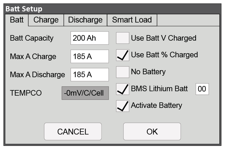
Closed-Loop Battery Setup > Battery (Two 130Ah AES Batteries with 12K-P)
|
Batt Setup > Batt |
|
|---|---|
|
Batt Capacity |
Set to the number of Discover Lithium batteries x Ah capacity of each. (For example, set to 200 Ah for two AES RACKMOUNT batteries, each rated at 100 Ah capacity). |
|
Max A Charge |
For a single inverter: set to the lesser of the inverter’s max charge capacity, or the quantity of attached batteries, multiplied by the battery model’s specific max charge rating. For example, a 12K-P inverter would be set to the lessor of the inverter’s max charge rate of 185 A, or 190 A for two AES RACKMOUNT 48-48-5120 batteries rated at 95 A max charge each. (2) For a three-phase system: set to the lessor of the max charge value for the master inverter, or the quantity of attached batteries multiplied by the battery model’s max charge rating, divided by the number of inverters. For example, the master 12K-P would be set to the lessor of the inverter’s max charge rate of 185A, or 126 A, for a battery bank of four AES RACKMOUNT 48-48-5120 batteries rated at 95 A max charge each (380 A divided by three inverters). NOTE: Each HELIOS ESS battery is rated at a 200 A charge rate, but when connected in parallel, the maximum current is limited by internal busbars. For the recommended maximum current for paralleled HELIOS ESS, refer to the HELIOS Manual, Minimum Specifications for Battery Systems. |
|
Max A Discharge |
For a single inverter: set to the lesser of the inverter’s max discharge capacity, or the quantity of attached batteries, multiplied by the battery model’s specific max discharge rating. For example, a 12K-P inverter would be set to the lessor of the inverter’s max discharge rate of 185 A, or 190 A for two AES RACKMOUNT 48-48-5120 batteries rated at 95 A max discharge each. (1) For a three-phase system: set to the lessor of the max discharge value for the master inverter, or the quantity of attached batteries multiplied by the battery model’s max discharge rating, divided by the number of inverters. For example, the master 12K-P would be set to the lessor of the inverter’s max discharge rate of 185 A, or 126 A, for a battery bank of four AES RACKMOUNT 48-48-5120 batteries rated at 95 A max discharge each (380 A divided by three inverters). NOTE: Each HELIOS ESS battery is rated at a 200 A discharge rate, but when connected in parallel, the maximum current is limited by internal busbars. For the recommended maximum current for paralleled HELIOS ESS, refer to the HELIOS Manual, Minimum Specifications for Battery Systems. |
|
TEMPCO |
This value is disabled (grey) when BMS Lithium Batt is enabled. |
|
Use Batt V Charged |
Disable |
|
Use Batt % Charged |
Enable |
|
No Battery |
Disable |
|
BMS Lithium Batt |
Enable and set to 00 (2) |
|
Activate Battery |
Enable |
|
(1) The recommended value for Max A Charge is 75% of the rated maximum charge current for the battery. (2) Setting the BMS Lithium Batt parameter to Enable confirms closed-loop operation. Ensure that a checkmark and 00 (CANBus Battery mode) is displayed. The values and parameters used are for an operating temperature of 25 °C (77 °F). |
|
Closed-Loop - Batt Setup > Charge
Touch the CHARGE tab onscreen to start the programming sequence (see image below).
-
Touch the OK button to save all onscreen values - Ignore data displayed in GREY boxes.
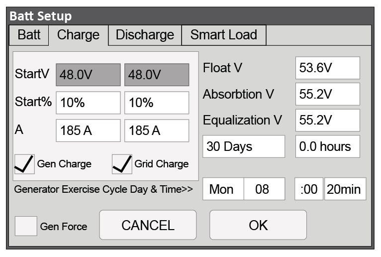
Closed-Loop Battery Setup > Charge (Two 100 Ah AES RACKMOUNT Batteries with 12K-P)
|
Batt Setup > Charge |
|
|---|---|
|
Gen Charge |
Enable if charging from a generator is desired. (1) Note: The Gen Input Breaker must be connected to the output of an AC generator for this work. |
|
Grid Charge |
Enable if charging from the grid is desired. (2) Note: The Grid Input Breaker must be connected to input from the grid for this to work. |
|
StartV |
Unavailable (Grey) in a closed-loop configuration. |
|
Start% |
Set to user preference based on battery State-of-charge as a percentage. The recommended minimum is 10%. |
|
A |
Set to the same Amp value that was set for Max A Charge. (3) |
|
Float V |
Value is communicated by BMS in a closed-loop configuration. Ignore the displayed value. |
|
Absorption V |
Value is communicated by BMS in a closed-loop configuration. Ignore the displayed value. |
|
Equalization V |
The function is disabled in a closed-loop configuration. Ignore the displayed value. |
|
Gen Exercise Cycle Day & Cycle |
Refer to Solar-Ark documentation. |
|
Gen Force |
Refer to Solar-Ark documentation. |
|
(1) Left column options are for Gen Charge AutoStart values (Reference Sol-Ark documentation for more details on the generator AutoStart function. (2) Right Column options are for Grid Charge values. (3) If need be, this value is used to curtail the maximum current output of the charger. The values and parameters used are for an operating temperature of 25 °C (77 °F). |
|
Closed-Loop - Batt Setup > Discharge
Touch the DISCHARGE tab onscreen to start the programming sequence (see Figure X.x).
-
Touch the OK button to save all onscreen values - Ignore data displayed in GREY boxes.
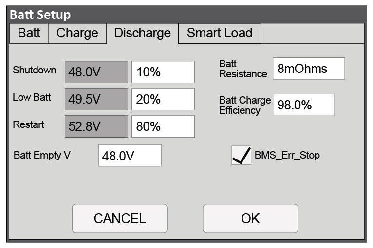
Closed-Loop Battery Setup > Discharge (Two 100 Ah AES RACKMOUNT Batteries with 12K-P)
|
Batt Setup > Discharge |
|
|---|---|
|
Shutdown |
Set to user preference based on battery State-of-charge as a percentage. The recommended minimum is 10%. (1) |
|
Low Batt |
Set to user preference based on battery State-of-charge as a percentage. The recommended minimum is 20%. (1) |
|
Restart |
Set to user preference based on battery State-of-charge as a percentage. (1) |
|
Batt Empty V |
48 V |
|
Batt Resistance |
Set to: Ten mOhm divided by the number of batteries (plus mOhm value for cable resistance, if known). (2) |
|
Batt Charge Efficiency |
98.0 % |
|
BMS_Err_Stop |
Enable (3) |
|
(1) A closed-loop configuration uses % state-of-charge. Discharge voltage values are not available. (2) This value should include cable and connection resistance. The formula provided is to assist with the calculation of a general value. (3) BMS_Err_Stop MUST be enabled to cause the inverter to stop operating if there is a communication error. If BMS_Err_Stop is disabled, the inverter will continue to operate using the last communicated battery values. The values and parameters used are for an assumed operating temperature of 25 °C (77 °F). |
|
Batt Setup > Smart Load
Optional functionality. See Sol-Ark documentation for details on use and setup.