
Setting Up Sol-Ark Open-Loop Configuration
As a precautionary measure, it is recommended to program the Sol-Ark inverter with the correct voltage-based open-loop parameters before setting up closed-loop parameters.
If necessary, first configure Sol-Ark inverters to operate in parallel by establishing the inverter master/slave relationships and phase designations before setting the parameters for battery operation. Configuring the master inverter will cascade parameters and settings to the slave inverters.
The Open-loop Configuration Procedure
Refer to the latest Discover Energy Systems documentation for battery values and the latest Sol-Ark documentation for details on menu navigation and the setup procedure.
Set the Discover Lithium batteries to ON and set the inverter to ON.
Using the touch screen and keypad on the inverter, navigate from the SYSTEM SETUP menu to the BATT SETUP menu screen.
Enable and disable parameters according to the instructions in the tables below.
Set each variable parameter according to the instructions in the tables below.
Touch the OK button to save all onscreen values - Ignore data displayed in GREY boxes.
NOTE |
|---|
Touch the Sol-Ark screen to:
Values are adjusted using the keypad. |
NOTE |
|---|
Enable parameters with a CHECKMARK, and disable parameters by leaving them unchecked. Touch a WHITE box onscreen to activate the adjustment of that value. Selecting parameters that have been enabled and disabled alters values that are available to be adjusted.
|
NOTE |
|---|
If necessary, configure Sol-Ark inverters to operate in parallel before setting the parameters for battery operation. |
Open-Loop - Batt Setup > Batt
Touch the BATT tab onscreen to start the programming sequence (see image below).
Touch the OK button to save all onscreen values – ignore data displayed in GREY boxes.
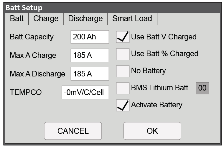
Open-Loop Battery Setup > Batt Menu (Two 100 Ah AES RACKMOUNT Batteries with 12K-P)
Batt Setup > Batt |
|
|---|---|
Batt Capacity | Set to the number of Discover Lithium batteries x Ah capacity of each. For example, set to 200 Ah (2 x 100 Ah) for two AES RACKMOUNT 48-48-5120 batteries. |
Max A Charge | For a single inverter: set to the lesser of the inverter’s max charge capacity, or the quantity of attached batteries, multiplied by the battery model’s specific max charge rating. For example, a 12K-P inverter would be set to the lessor of the inverter’s max charge rate of 185 A, or 190 A for two AES RACKMOUNT 48-48-5120 batteries rated at 95 A max charge each.(1) For a three-phase system: set to the lessor of the max charge value for the master inverter, or the quantity of attached batteries, multiplied by the battery model’s max charge rating, divided by the number of inverters. For example, the master 12K-P would be set to the lessor of the inverter’s max charge rate of 185 A, or 126 A, for four AES RACKMOUNT 48-48-5120 batteries rated at 95 A max charge each (380 A divided by three inverters). NOTE: Each HELIOS ESS battery is rated at a 200 A charge rate, but when connected in parallel, the maximum current is limited by internal busbars. For the recommended maximum current for paralleled HELIOS ESS, refer to the HELIOS Manual, Minimum Specifications for Battery Systems. |
Max A Discharge | For a single inverter: set to the lesser of the inverter’s max discharge capacity, or the quantity of attached batteries, multiplied by the battery model’s specific max discharge rating. For example, a 12K-P inverter would be set to the lessor of the inverter’s max discharge rate of 185 A, or 190 A for two AES RACKMOUNT 48-48-5120 batteries rated at 95 A max charge each.(1) For a three-phase system: set to the lessor of the max discharge value for the master inverter, or the quantity of attached batteries multiplied by the battery model’s max discharge rating, divided by the number of inverters. For example, the master 12K-P would be set to the lessor of the inverter’s max discharge rate of 185 A, or 126 A, for a battery bank of four AES RACKMOUNT 48-48-5120 batteries rated at 95 A max discharge each (380 A divided by three inverters). NOTE: Each HELIOS ESS battery is rated at a 200 A discharge rate, but when connected in parallel, the maximum current is limited by internal busbars. For the recommended maximum current for paralleled HELIOS ESS, refer to the HELIOS Manual, Minimum Specifications for Battery Systems. |
TEMPCO | Set to 0 mv/C/Cell. (2) |
Use Batt V Charged | Enable |
Use Batt % Charged | Disable |
No Battery | Disable |
BMS Lithium Batt | Disable (Displays 00 value) (3) |
Activate Battery | Enable |
(1) The recommended value for Max A Charge is 75% of the rated maximum charge current for the battery. (2) Discover Lithium batteries do not require temperature compensation. Setting TEMPCP to O mv/C/Cell will disable inverter-charger controlled temperature compensation. (3) Setting the BMS Lithium Batt parameter to Disable confirms open-loop operation. Setting the parameter to Enable confirms closed-loop operation. The values and parameters used are for an assumed operating temperature of 25 °C (77 °F). | |
Open-Loop - Batt Setup > Charge
Touch the CHARGE tab onscreen to start the programming sequence (see image below).
Touch the OK button to save all onscreen values - Ignore data displayed in GREY boxes.
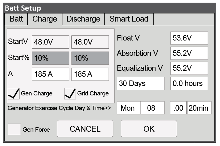
Open-Loop Battery Setup > Charge (Two 100 Ah AES RACKMOUNT Batteries with 12K-P)
Batt Setup > Charge |
|
|---|---|
Gen Charge | Enable if charging from a generator is desired. (1) Note: The Gen Input Breaker must be connected to the output of an AC generator for this work. |
Grid Charge | Enable if charging from the grid is desired. (2) Note: The Grid Input Breaker must be connected to input from the grid for this to work. |
StartV | Set the value to the desired battery voltage that will trigger battery charging. The absolute minimum is 48 V. |
Start% | Unavailable (Grey) in an open-loop configuration. |
A | Set to the same Amp value that was used for Max A Charge. (3) |
Float V | Set to 53.6 V |
Absorption V | Set to 55.2 V (4) |
Equalization V | 55.2 V (5) 30 days 0.0 hours (5) |
Gen Exercise Cycle Day & Cycle | Refer to Solar-Ark documentation. |
Gen Force | Refer to Solar-Ark documentation. |
(1) Left column options are for Gen Charge AutoStart values (Reference Sol-Ark documentation for more details on the generator AutoStart function. (2) Right Column options are for Grid Charge values. (3) If need be, this value is used to curtail the maximum current output of the charger. (4) Absorption will stop at 2% of the set capacity of the battery bank and move to the float value. (5) Lithium batteries MUST not be equalized. Using a value of 55.2 for Equalization V and zero for Hours ensures that the batteries will not be equalized. The values and parameters used are for an operating temperature of 25 °C (77 °F). | |
Open-Loop - Batt Setup > Discharge
Touch the DISCHARGE tab onscreen to start the programming sequence (see image below).
Touch the OK button to save all onscreen values - Ignore data displayed in GREY boxes.
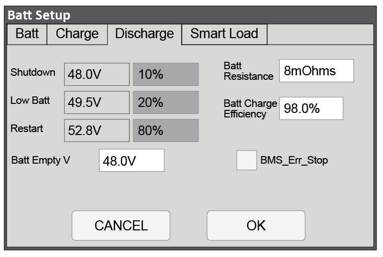
Open-Loop Battery Setup > Discharge (Two 100Ah AES RACKMOUNT Batteries with 12K-P)
Batt Setup > Discharge |
|
|---|---|
BMS_Err_Stop | Disable |
Shutdown | 48.0 V (1) |
Low Batt | 49.5 V (1) |
Restart | 52.8 V (1) |
Batt Empty V | 48.0 V |
Batt Resistance | Set to: Ten mOhm divided by the number of batteries, plus the mOhm value of resistance for interconnection and homerun cabling. (2) |
Batt Charge Efficiency | 98.0 % |
(1) Discharge state-of-charge percentage values are unavailable in an open-loop (voltage-based) configuration. (2) This value should include cable and connection resistance. The formula is provided to assist with the calculation of a general value. The values and parameters used are for an operating temperature of 25 °C (77 °F). | |