
There are three standard inverter-to-cabinet configurations.
-
1 Inverter: 1 Cabinet
One Sol-Ark 3-Phase Inverter, One AES Cabinet -
2 Inverters: 1 Cabinet
Two Sol-Ark 3-Phase Inverters, One AES Cabinet -
1 Inverter: 2 Cabinets
One Sol-Ark 3-Phase Inverter, Two AES Cabinets
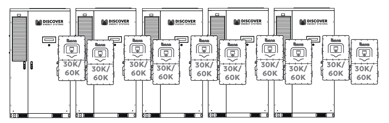
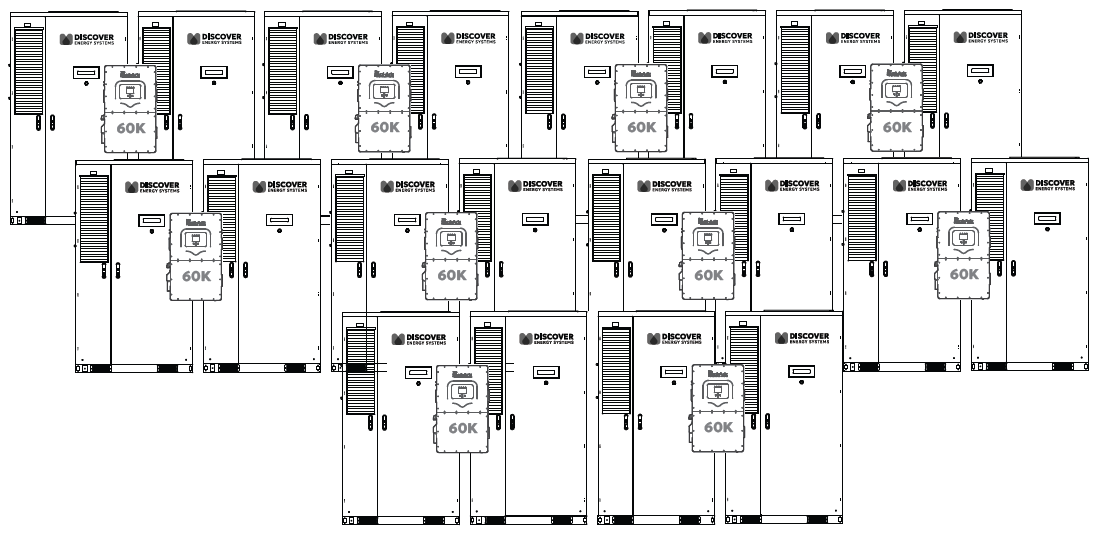
Systems can scale up to 10 Sol-Ark 30K/60K-3P inverters in parallel on the AC bus, supporting a total inverter output of up to 300-600 kW.
When designing larger systems, maintain consistent inverter-to-cabinet ratios across the entire installation. For example, if your system starts with a 1:1 ratio (one inverter per cabinet), all additional inverter-cabinet sets should follow the same 1:1 pattern.
|
NOTICE |
|---|
|
UNBALANCED BATTERY HAZARD Mixing ratios within the same system (e.g., combining 1:1 and 1:2 configurations) is not supported, as it can lead to unbalanced load sharing. Failure to follow these instructions may result in equipment damage. |
One Sol-Ark 3-Phase Inverter, One AES Cabinet
|
|
|---|
|
ELECTRIC SHOCK AND FIRE HAZARD Follow NEC guidelines for conductor size, insulation rating (≥1000 Vdc), and torque specs for safe and code-compliant installation. Failure to follow these instructions may result in death or serious injury. |
One Sol-Ark 30K/60K-3P Inverter, One AES Battery Cabinet
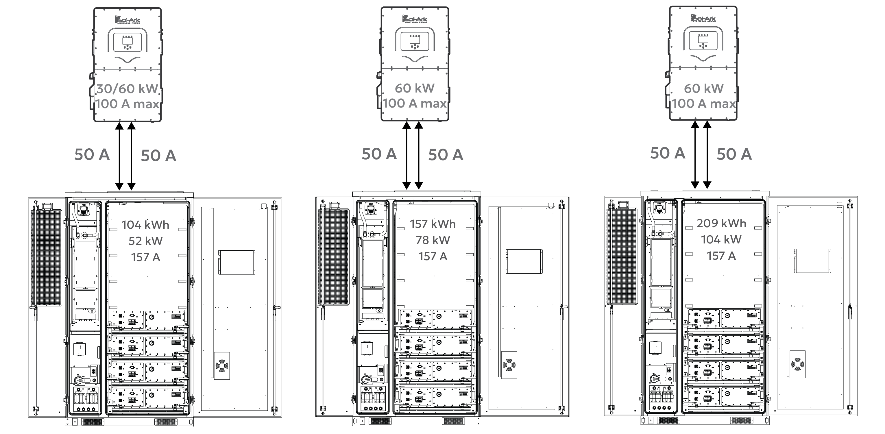
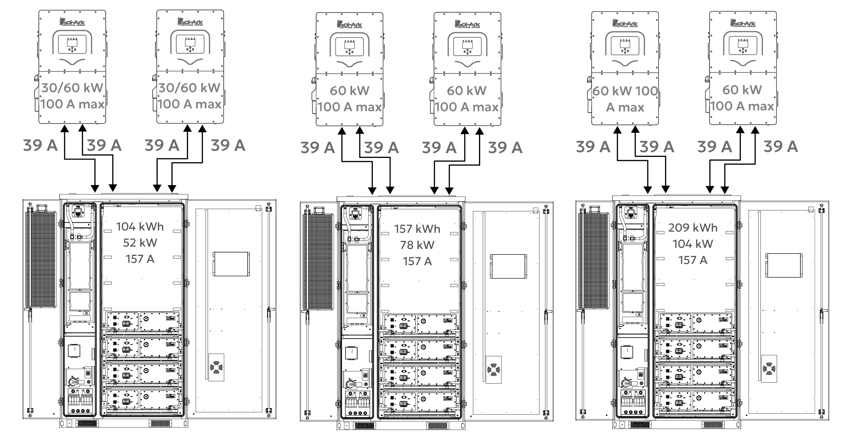
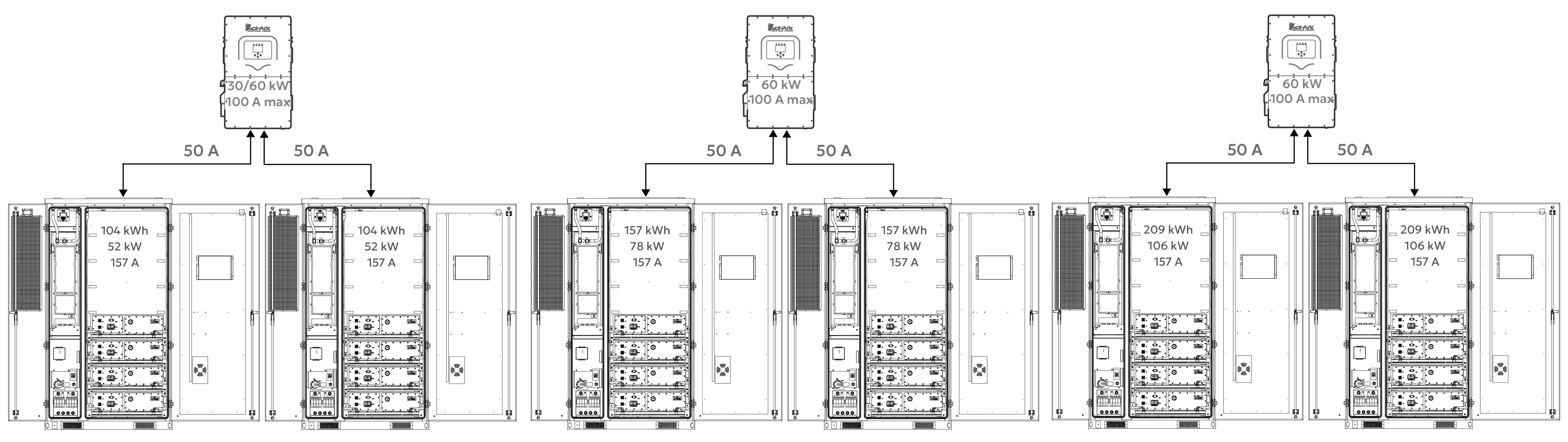
When paired with a single Sol-Ark 30K/60K inverter, the AES Cabinet’s maximum continuous current limit is 157 A, operating within its rated 52 / 78 / 104 kW continuous output limit. Actual discharge performance depends on the inverter model’s battery-side power capacity, as shown below.
Full Load Duration
|
Inverter Model |
Battery Discharge Limit |
CAB-106
|
CAB-160
|
CAB-210 Estimated run time |
|---|---|---|---|---|
|
30K-3P-208V |
30 kW |
~3½ hours
|
N/A |
N/A |
|
60K-3P-480V |
60 kW |
~2 hours
|
~2½ hours
|
~3½ hours
|
* Curtailed by the battery
These run time estimates assume continuous full-power discharge and operation within safe continuous discharge parameters. Final performance should match the site's energy demand and load profile.
System Scalability – One Inverter, One AES Cabinet
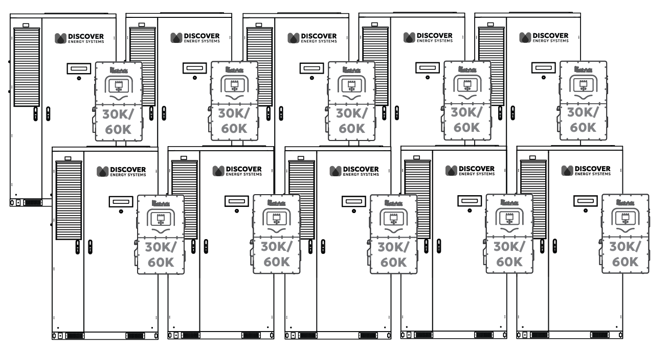
Ten Paralleled Inverters
Each Sol-Ark 30K/60K-3P inverter is paired with one AES Cabinet.
In this setup:
-
104/209 kWh of usable backup energy per inverter
-
Discharge power limited by the inverter model (30/60 kW)
-
Up to ten inverters can be connected in parallel on the backup side, providing up to 300-600 kW of continuous backup power and approximately 1.06–2.12 MWh of total backup energy (10 × 104 kWh / 10 × 209 kWh).
Grid-Tied (Non-Backup) Scalability
The number of inverters or batteries is unlimited for non-backup use. Each inverter runs independently, allowing systems to scale as large as needed for energy shifting, peak shaving, or other grid-interactive applications.
DC Battery Wiring - One Inverter, One AES Cabinet
The inverter’s battery input terminals are connected to the AES Cabinet using two pairs of 50 A conductors (two positive and two negative cables).
Inverter to Cabinet DC Wiring
Each Sol-Ark 30K/60-3P inverter has two battery input terminals, each rated up to 50 A. The AES Cabinet connects using two positive and two negative conductors, each protected by a 70 A fuse in the AES Cabinet’s built-in DC distribution box.
This setup ensures balanced current flow to each of the inverter’s internal DC/DC converters and supports continuous discharge of 30 or 60 kW.
Communication – One Inverter, One AES Cabinet
Inverter - LYNK II - Cabinet Communication
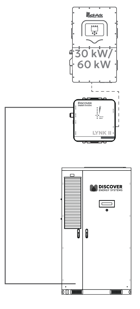
In a one-to-one configuration, the AES Cabinet communicates with the Sol-Ark inverter through the LYNK II Gateway, enabling real-time, closed-loop control.
-
Use standard CAT6 or higher Ethernet cables, wired in a straight-through configuration with RJ45 plugs on both ends.
-
Connect one cable from the LYNK II’s CAN port to the Sol-Ark inverter's BMS1 port.
-
Connect a second cable from the LYNK port on the LYNK II Gateway to the J3/J4 port on the AES Cabinet’s High Voltage Box. On most AES Cabinets, a CAT6 cable is already connected to the J3 port on the AES Cabinet’s High Voltage Box and is accessible from the LYNK II.
This communication link enables the inverter to receive live battery data, including state of charge, voltage, current, temperature, and charge/discharge limits, for safe, accurate, and optimized operation.
Two Sol-Ark 3-Phase Inverters, One AES Cabinet
|
|
|---|
|
ELECTRIC SHOCK AND FIRE HAZARD
Failure to follow these instructions may result in death or serious injury. |
Two Sol-Ark Inverters, One AES Battery Cabinet
When the AES Cabinet is paired with two Sol-Ark inverters, the AES Cabinet may limit the inverters to a maximum continuous output of 52/104 kW. Actual discharge performance depends on the inverter model’s battery-side power capacity, as shown below.
|
Inverter Model |
Battery Discharge Limit |
CAB-106
|
CAB-160
|
CAB-210 Estimated run time |
|---|---|---|---|---|
|
30K-3P-208V |
30 kW × 2 = 60 kW |
~2 hours
|
N/A |
N/A |
|
60K-3P-480V |
60 kW × 2 = 120 kW |
~2 hours
|
~2 hours
|
~2 hours
|
* Curtailed by the battery.
These run time estimates assume continuous full-power discharge and operation within safe continuous discharge parameters. Final performance should match the site's energy demand and load profile.
System Scalability - Two Inverters, One AES Cabinet
Ten Paralleled Inverters
Two Sol-Ark 30K/60K-3P inverters are paired with each AES battery cabinet.
In this setup:
-
104 to 209 kWh of usable backup energy between two inverters
-
Discharge power is limited by the total inverter capacity or battery power limitation (max 52 to 120 kW)
-
On the backup side, up to ten inverters can be connected in parallel, providing 300-600 kW of continuous backup power and approximately 520-1,045 kWh of total backup energy (5 × 10⁴ kWh / 5 × 209 kWh).
Grid-Tied (Non-Backup) Scalability
The number of inverters or batteries is unlimited for non-backup use. Each inverter runs independently, allowing systems to scale as large as needed for energy shifting, peak shaving, or other grid-interactive applications.
DC Battery Wiring – Two Inverters, One AES Cabinet
Inverter to Cabinet DC Wiring
Each Sol-Ark 3P inverter has two battery input terminals, each rated at 50 A. The AES Cabinet connects to the inverter using:
-
Two positive and two negative #4 AWG conductors to each inverter.
-
Each conductor is protected by a 70 A fuse in the AES Cabinet’s built-in DC distribution box.
This setup ensures balanced current flow to each inverter’s internal DC/DC converter and supports 30-60 kW continuous charge/discharge, depending on the inverter model.
Communication – Two Inverters, One AES Cabinet
Inverter - LYNK II - Cabinet Communication
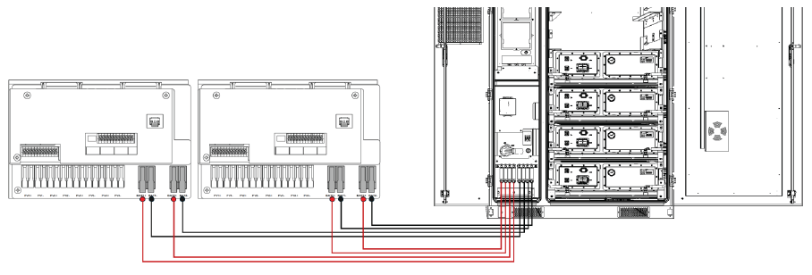
In a two-to-one configuration, a LYNK II Gateway is required for each inverter to enable real-time, managed (closed-loop) control. The AES Cabinet communicates with one Sol-Ark inverter through one LYNK II Gateway (may be included with the battery cabinet), and with a second Sol-Ark inverter through a second LYNK II Gateway.
Wiring
-
Connect one cable from LYNK II #1 CAN port to the Sol-Ark inverter #1’s BMS port. Connect a second cable from LYNK II #1’s LYNK port to the J3 port on the AES Cabinet’s High Voltage Box. On most AES Cabinets, a CAT6 cable is already connected to the J3 port on the AES Cabinet’s High Voltage Box and is accessible from the LYNK II.
-
Connect a third cable from LYNK II #2 CAN port to the Sol-Ark inverter #2’s BMS port. Connect a fourth cable from LYNK II #2’s LYNK port to the J4 port on the AES Cabinet’s High Voltage Box.
|
NOTE |
|
You can use a splitter/combiner, as shown below, to connect two LYNK II Gateways to the J3/J4 ports on the AES Cabinet through a single cable. 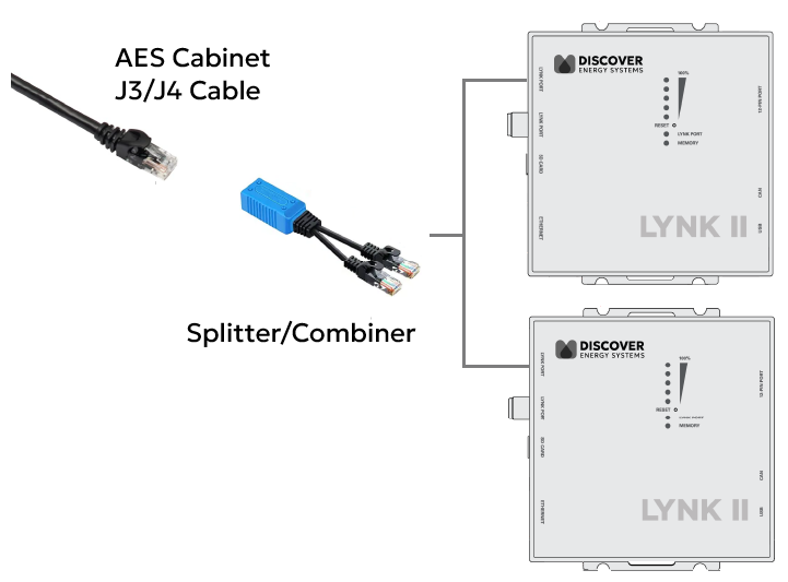
|
Configure LYNK II
-
Start LYNK ACCESS 2.5.0 or later and update both LYNK II Gateways to firmware to 2.5.0 or later.
-
Connect to the first LYNK II device. From the LYNK ACCESS software’s LYNK tab, open the Cabinet Settings tile, enable Multi-LYNK, and set it as Primary.
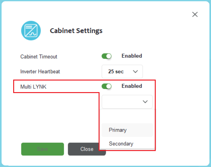
-
Connect to the second LYNK II device, enable Multi-LYNK and set it as Secondary.
To confirm the system is working correctly, check the battery charging current values on inverter. If values are 50% of the max, then the 2:1 Multi LYNK configuration is successful.
|
NOTE |
|---|
|
The LYNK II communication link enables the inverter to receive real-time battery data, including state of charge, voltage, current, temperature, and charge/discharge limits, ensuring safe, accurate, and optimized operation.
This setup enables two inverters to manage and monitor the battery cabinet, receiving real-time data for state of charge, voltage, current, temperature, and charge/discharge limits from each LYNK II Gateway. Two independent LYNK II Gateways ensure precise, safe, and optimized performance with dual inverters.
One Sol-Ark 3-Phase Inverter, Two AES Cabinets
|
|
|---|
|
ELECTRIC SHOCK AND FIRE HAZARD Follow NEC guidelines for conductor size, insulation rating (≥1000 Vdc), and torque specs for safe and code-compliant installation. Failure to follow these instructions may result in death or serious injury. |
One Sol-Ark Inverter, Two AES Battery Cabinets
When two AES Cabinets are paired with a single Sol-Ark 3-phase inverter, the AES Cabinets' maximum continuous current limit is 157 A, operating within their rated 209 / 314 / 418 kWh continuous output limit. Actual discharge performance depends on the inverter model’s battery-side power capacity, as shown below.
|
Inverter Model |
Discharge Power Limit |
2 × CAB-106
|
2 × CAB-160
|
2 × CAB-210 Estimated run time |
|---|---|---|---|---|
|
30K-3P-208V |
30 kW |
~7 hours
|
N/A |
N/A |
|
60K-3P-480V |
60 kW |
~3½ hours
|
~5¼ hours
|
~7 hours
|
* Curtailed by the battery
These run times assume continuous full-power discharge at the inverter's rated limit. While the inverter determines the maximum power output, the dual-cabinet setup extends runtime. Dual cabinets increase total stored energy and are ideal for longer-duration backup or deeper cycling in time-of-use and peak-shaving applications.
System Scalability – One Inverter, Two AES Cabinets
The Sol-Ark system-level scalability supports up to 10 inverters paralleled on the AC bus. This configuration allows for a maximum power output of 300-600 kW and energy storage of up to 4.24 MWh across all 10 inverters.
Parallel Inverters
Each Sol-Ark inverter can be paired with two AES battery cabinets, doubling the usable energy per inverter while maintaining discharge power based on inverter size.
In this setup:
-
209 / 314 / 418 kWh of usable backup energy per inverter (2 × 10⁴ kWh / 2 × 157 / 2 × 209 kWh)
-
Discharge power limited by the inverter (30/60 kW)
-
Up to ten inverters can be connected in parallel on the backup side, supporting 300-600 kW of backup power and approximately 2.1–4.2 MWh of total backup energy (10 × 209 kWh / 10 × 314 kWh / 10 × 418 kWh).
Grid-Tied (Non-Backup) Scalability
For grid-tied applications, the number of batteries or inverters is not limited. Each inverter operates independently, enabling large-scale deployments for energy arbitrage, load shifting, or demand charge reduction without backup power constraints.
DC Battery Wiring - One Inverter, Two AES Cabinets
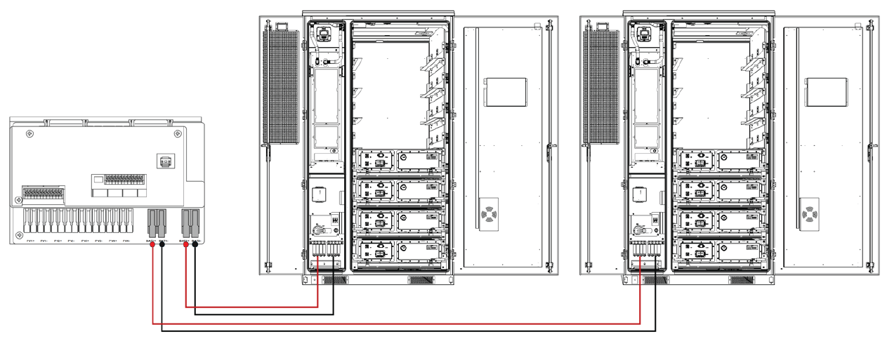
Inverter to Cabinet DC Wiring
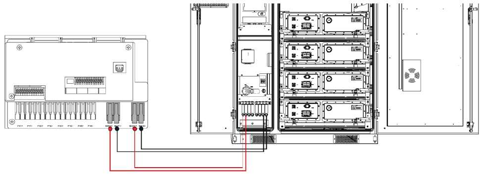
When connecting two AES battery cabinets to a single Sol-Ark inverter, each cabinet is wired to a dedicated battery input terminal:
-
Battery 1 connects to the inverter’s BAT1 terminals
-
Battery 2 connects to the inverter’s BAT2 terminals
The inverter’s integrated dual DC/DC converters are independently fused and control each input, allowing the inverter to manage each battery cabinet separately while balancing charge and discharge as needed.
Always follow NEC guidelines for conductor sizing, 1,000 Vdc insulation rating, proper torque values, and verify polarity before energizing the system.
Communication – One Inverter, Two AES Cabinets
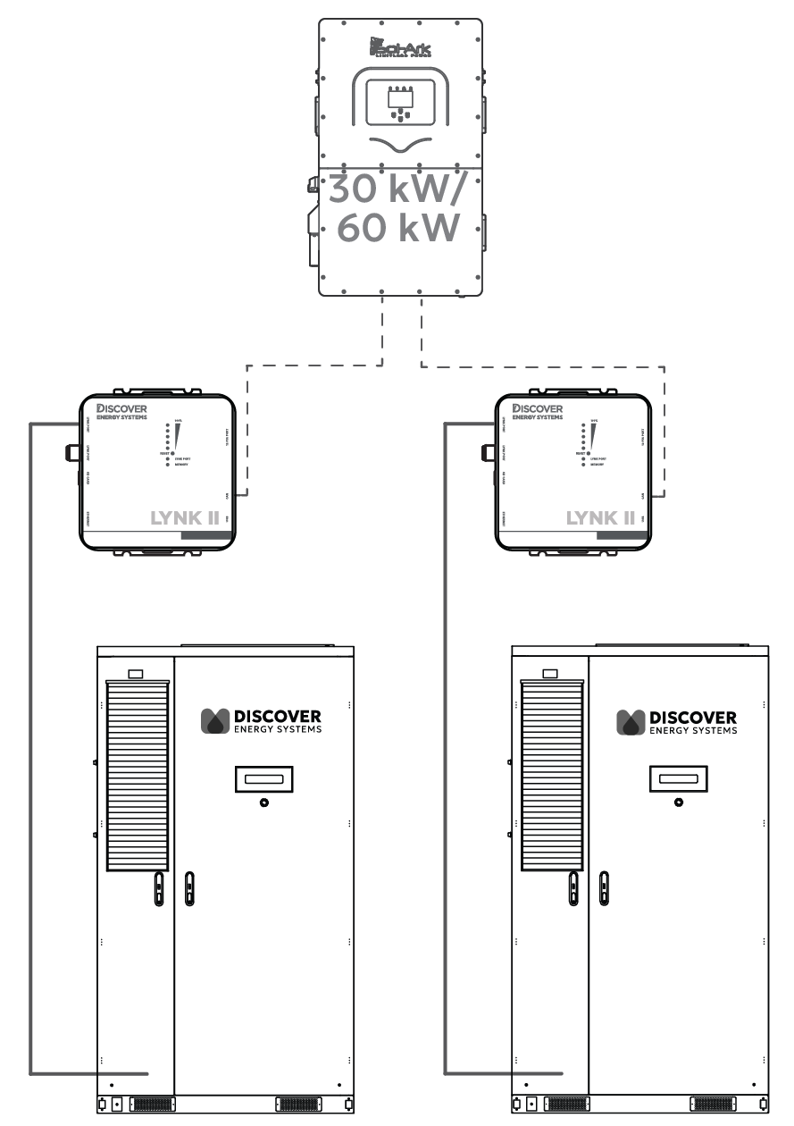
Inverter - LYNK II - Cabinet Communication
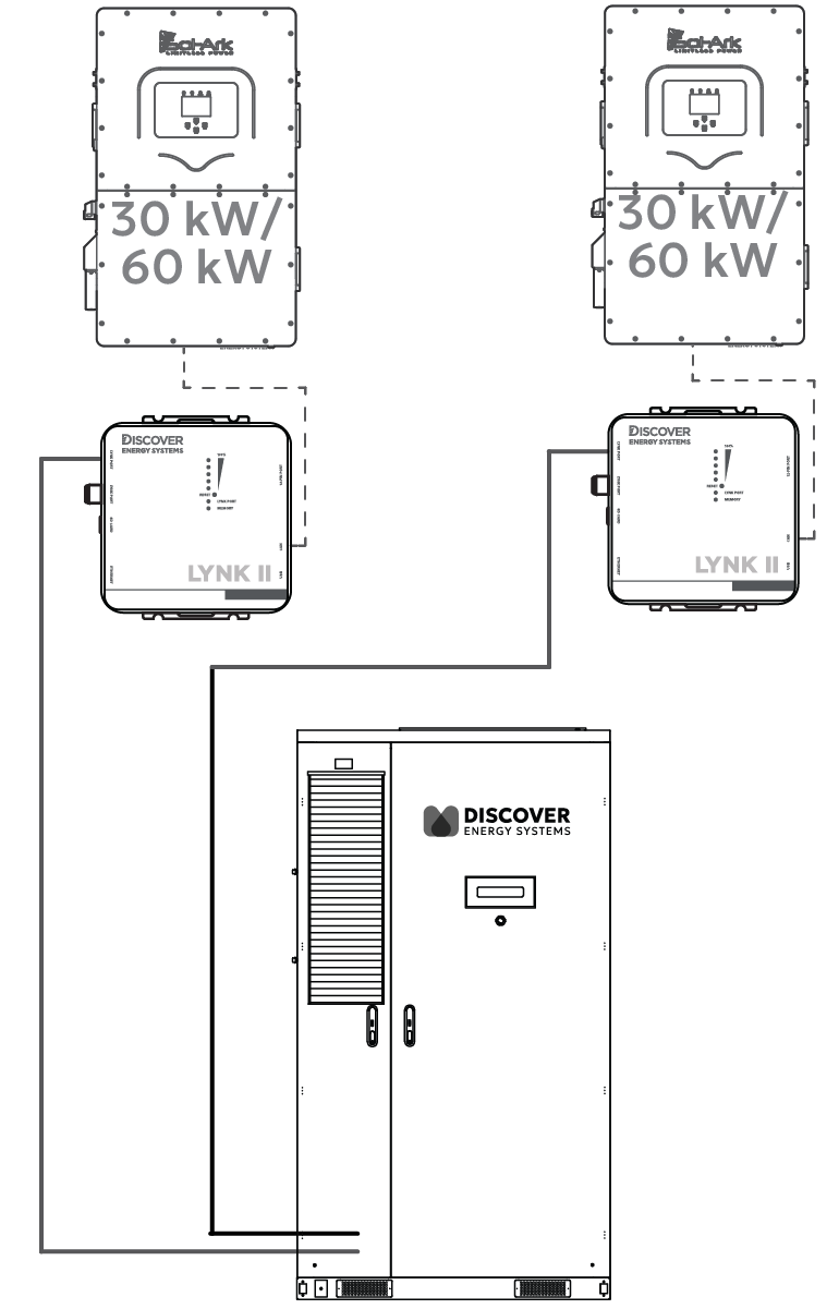
Each AES battery cabinet uses its own LYNK II Gateway for closed-loop communication with the Sol-Ark inverter in a two-to-one configuration. The inverter’s two BMS ports (BMS1 and BMS2) allow it to communicate with each battery independently.
-
Use standard CAT6 or higher Ethernet cables, wired in a straight-through configuration with RJ45 plugs on both ends.
-
Connect one cable from LYNK II #1 CAN port to the Sol-Ark inverter’s BMS1 port. Connect another cable to LYNK II #1’s LYNK port to the J3/J4 port on the AES Cabinet’s High Voltage Box. On most AES Cabinets, a CAT6 cable is already connected to the J3 port on the AES Cabinet’s High Voltage Box and is accessible from the LYNK II.
-
Connect a third cable from LYNK II #2 CAN port to the Sol-Ark inverter’s BMS2 port. Connect a fourth cable from LYNK II #2’s LYNK port to the J3/J4 port on the AES Cabinet’s High Voltage Box.
This setup enables the inverter to independently manage and monitor both battery cabinets, receiving real-time data for state of charge, voltage, current, temperature, and charge/discharge limits from each LYNK II Gateway. Two independent LYNK II Gateways ensure precise, safe, and optimized performance across both battery units.