
If closed-loop communication cannot be established and you need to resume operation, you may have to manually convert the Sunsynk inverter-charger to an open-loop configuration. Refer to the latest Discover Lithium battery documentation for battery values and the latest Sunsynk documentation for details on menu navigation and the setup procedure.
|
NOTE |
|---|
|
Depending on your system and particular use case, there may be other settings that require configuration. Refer to the inverter manual for information on these settings. |
-
Set the Discover Lithium batteries to ON and set the inverter-charger to ON.
-
Using the touch screen and keypad on the inverter-charger, navigate to Main Screen > System Setup > Battery Setup.
-
Specify the battery settings according to the instructions in the tables that follow.
-
Touch the OK button to save changes.
-
Exit and restart the inverter-charger.
|
NOTE |
|---|
|
If using multiple inverter-chargers, configure SUNSYNK inverter-chargers to operate in parallel before setting the parameters for battery operation. |
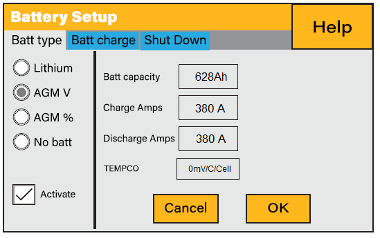
Open Loop - Batt Type
The SUNSYNK inverter-charger will operate in a open-loop configuration using voltage-based parameters if the BMS Lithium Batt parameter is disabled and the AGM V parameter is enabled.
Sunsynk Battery Setup for 2 x HELIOS ESS Batteries
|
Batt type |
|
|---|---|
|
Batt type |
Select the AGM V option. |
|
Activate |
Select this check box. |
|
Batt Capacity |
Set to the number of Discover Lithium batteries x Ah capacity of each. For example, set to 628 Ah (2 x 314 Ah) for two HELIOS ESS 52-48-16000 batteries. |
|
Charge Amps |
For a single inverter-charger, set to the lesser of the inverter-charger’s maximum charge rate or the quantity of attached batteries multiplied by the battery’s maximum charge rating. For example: Single phase system with 8K-SG05LP1 inverter-charger and two HELIOS ESS 52-48-16000 batteries:
Three-phase system with three 8K-SG04LP3 inverter-chargers and two HELIOS ESS 52-48-16000 batteries:
|
|
Discharge Amps |
For a single inverter-charger, set to the lesser of the inverter-charger’s maximum discharge rate or the quantity of attached batteries multiplied by the battery’s maximum discharge rating.
For a three-phase system with three inverter-chargers, set to the lesser value between the master inverter-charger’s maximum discharge rate or the quantity of attached batteries multiplied by the battery’s maximum discharge rate divided by the number of inverter-chargers. For example, set the 8K-SG04LP3 inverter-charger to the lesser of the inverter-charger’s maximum discharge rate of 190 A, or 133 A for two HELIOS ESS 52-48-16000 batteries that are each rated at a maximum discharge rate of 200 A and then divided by 3 inverters (2 x 200 A ÷ 3 = 133.33 A). |
|
TEMPCO |
Set to 0 mv/C/Cell. (2) |
(1) SUNSYNK’s recommended maximum battery value for Charge Amps is 75% of the battery’s rated maximum charge current.
(2) Discover Lithium batteries do not require temperature compensation. Setting TEMPCO to 0 mv/C/Cell disables inverter-charger controlled temperature compensation.
Open Loop - Batt Charge
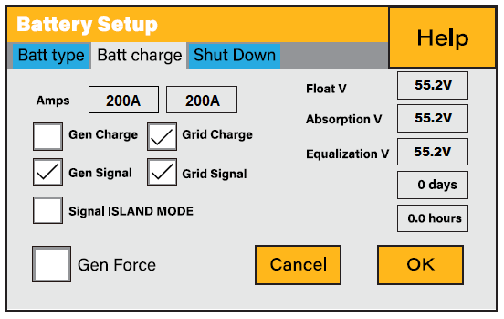
Sunsynk Battery Charge Settings
|
Batt charge |
|
|---|---|
|
Float V Absorption V Equalization V |
Set the suggested voltage values defined in the associated battery manual. Discover Lithium batteries must not be equalized. Setting zero hours ensures the batteries will not be equalized. |
Open Loop - Shutdown
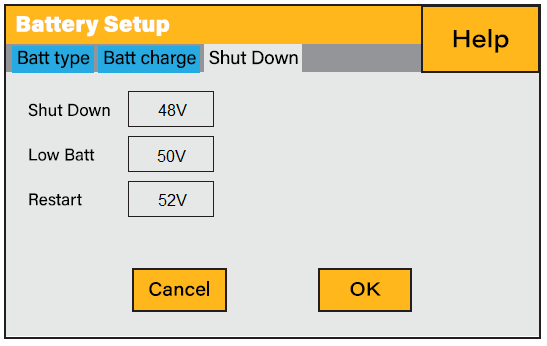
Sunsynk Battery Shutdown Settings
|
Shut Down |
|
|---|---|
|
Shut Down Low Batt Restart |
48 V 50 V 52 V |
|
NOTE |
|---|
|
For more information about configuring the Sunsynk inverter-charger, refer to product documentation on the Sunsynk website (sunsynk.org) or the LYNK II Installation and User Manual (805-0033). |