
Two Sol-Ark 3-Phase Inverters, One AES Cabinet
|
|---|
ELECTRIC SHOCK AND FIRE HAZARD Failure to follow these instructions may result in death or serious injury. |
Two Sol-Ark Inverters, One AES Battery Cabinet
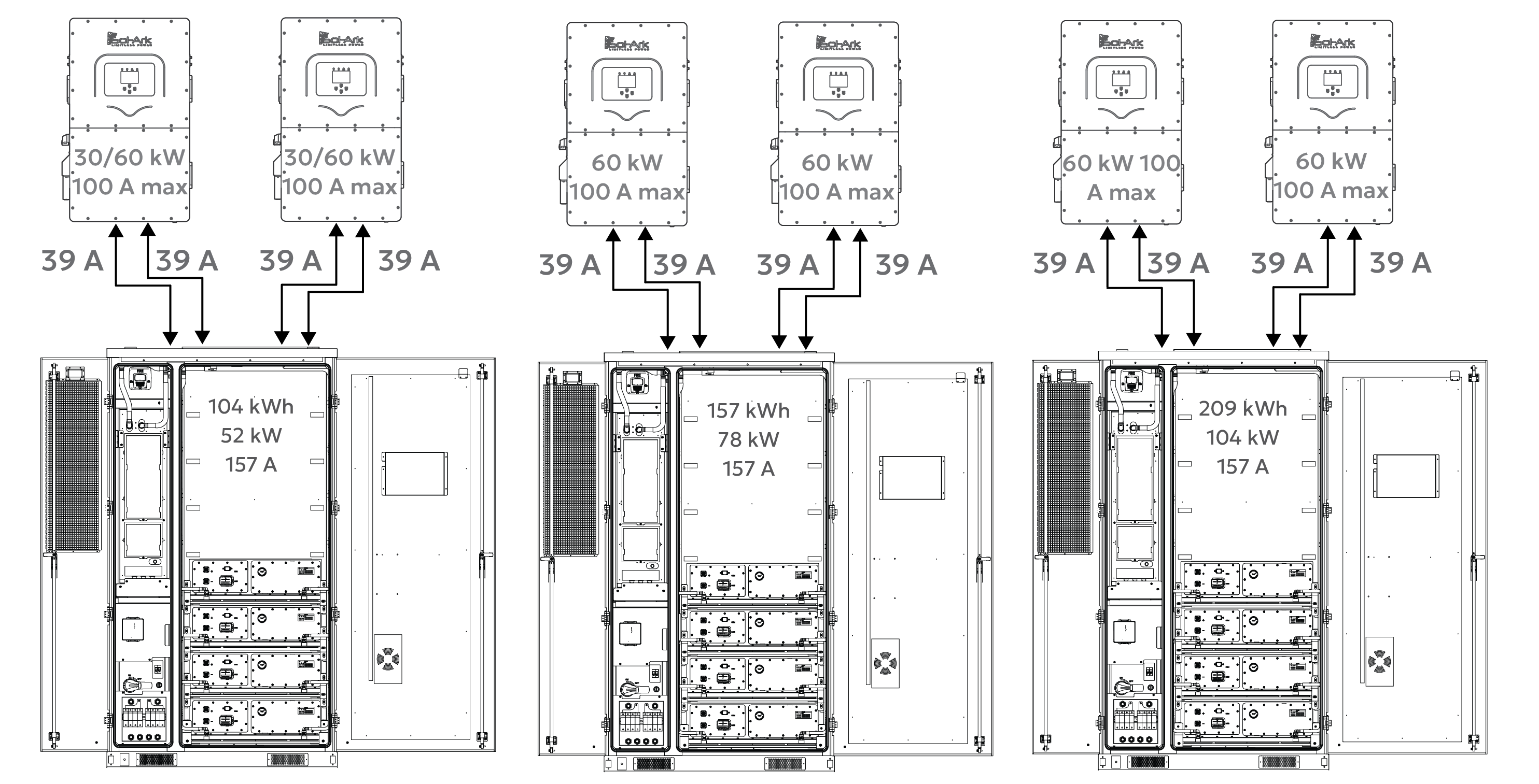
When the AES Cabinet is paired with two Sol-Ark inverters, the AES Cabinet may limit the inverters to a maximum continuous output of 52/104 kW. Actual discharge performance depends on the inverter model’s battery-side power capacity, as shown below.
Inverter Model | Battery Discharge Limit | CAB-106 | CAB-160 | CAB-210 Estimated run time |
|---|---|---|---|---|
30K-3P-208V | 30 kW × 2 = 60 kW | ~2 hours | N/A | N/A |
60K-3P-480V | 60 kW × 2 = 120 kW | ~2 hours | ~2 hours | ~2 hours |
* Curtailed by the battery.
These run time estimates assume continuous full-power discharge and operation within safe continuous discharge parameters. Final performance should match the site's energy demand and load profile.
System Scalability - Two Inverters, One AES Cabinet
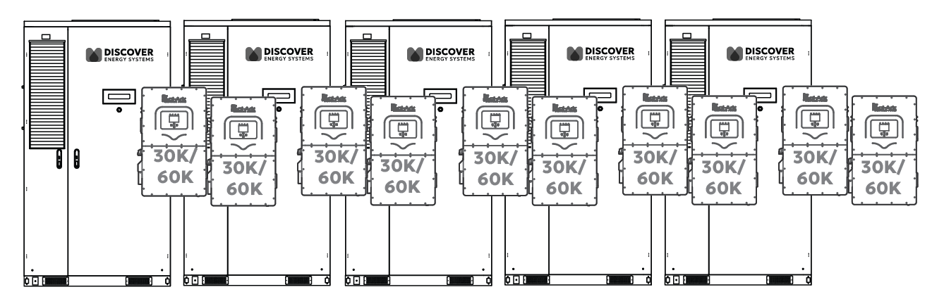
Ten Paralleled Inverters
Two Sol-Ark 30K/60K-3P inverters are paired with each AES battery cabinet.
In this setup:
104 to 209 kWh of usable backup energy between two inverters
Discharge power is limited by the total inverter capacity or battery power limitation (max 52 to 120 kW)
On the backup side, up to ten inverters can be connected in parallel, providing 300-600 kW of continuous backup power and approximately 520-1,045 kWh of total backup energy (5 × 10⁴ kWh / 5 × 209 kWh).
Grid-Tied (Non-Backup) Scalability
The number of inverters or batteries is unlimited for non-backup use. Each inverter runs independently, allowing systems to scale as large as needed for energy shifting, peak shaving, or other grid-interactive applications.
DC Battery Wiring – Two Inverters, One AES Cabinet
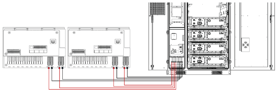
Inverter to Cabinet DC Wiring
Each Sol-Ark 3P inverter has two battery input terminals, each rated at 50 A. The AES Cabinet connects to the inverter using:
Two positive and two negative #4 AWG conductors to each inverter.
Each conductor is protected by a 70 A fuse in the AES Cabinet’s built-in DC distribution box.
This setup ensures balanced current flow to each inverter’s internal DC/DC converter and supports 30-60 kW continuous charge/discharge, depending on the inverter model.
Communication – Two Inverters, One AES Cabinet
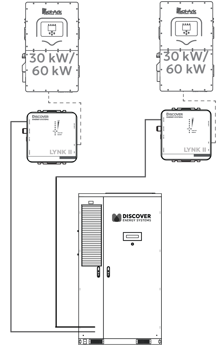
Inverter - LYNK II - Cabinet Communication
In a two-to-one configuration, a LYNK II Gateway is required for each inverter to enable real-time, managed (closed-loop) control. The AES Cabinet communicates with one Sol-Ark inverter through one LYNK II Gateway (may be included with the battery cabinet), and with a second Sol-Ark inverter through a second LYNK II Gateway.
Wiring
Connect one cable from LYNK II #1 CAN port to the Sol-Ark inverter #1’s BMS port. Connect a second cable from LYNK II #1’s LYNK port to the J3 port on the AES Cabinet’s High Voltage Box. On most AES Cabinets, a CAT6 cable is already connected to the J3 port on the AES Cabinet’s High Voltage Box and is accessible from the LYNK II.
Connect a third cable from LYNK II #2 CAN port to the Sol-Ark inverter #2’s BMS port. Connect a fourth cable from LYNK II #2’s LYNK port to the J4 port on the AES Cabinet’s High Voltage Box.
NOTE |
You can use a splitter/combiner, as shown below, to connect two LYNK II Gateways to the J3/J4 ports on the AES Cabinet through a single cable.  |
Configure LYNK II
Start LYNK ACCESS 2.5.0 or later and update both LYNK II Gateways to firmware to 2.5.0 or later.
Connect to the first LYNK II device. From the LYNK ACCESS software’s LYNK tab, open the Cabinet Settings tile, enable Multi-LYNK, and set it as Primary.
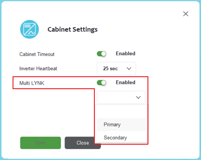
Connect to the second LYNK II device, enable Multi-LYNK and set it as Secondary.
To confirm the system is working correctly, check the battery charging current values on inverter. If values are 50% of the max, then the 2:1 Multi LYNK configuration is successful.
NOTE |
|---|
|
The LYNK II communication link enables the inverter to receive real-time battery data, including state of charge, voltage, current, temperature, and charge/discharge limits, ensuring safe, accurate, and optimized operation.
This setup enables two inverters to manage and monitor the battery cabinet, receiving real-time data for state of charge, voltage, current, temperature, and charge/discharge limits from each LYNK II Gateway. Two independent LYNK II Gateways ensure precise, safe, and optimized performance with dual inverters.