
|
NOTICE |
|---|
|
EQUIPMENT DAMAGE
|
Do Not Parallel Battery Cabinets on the DC Bus
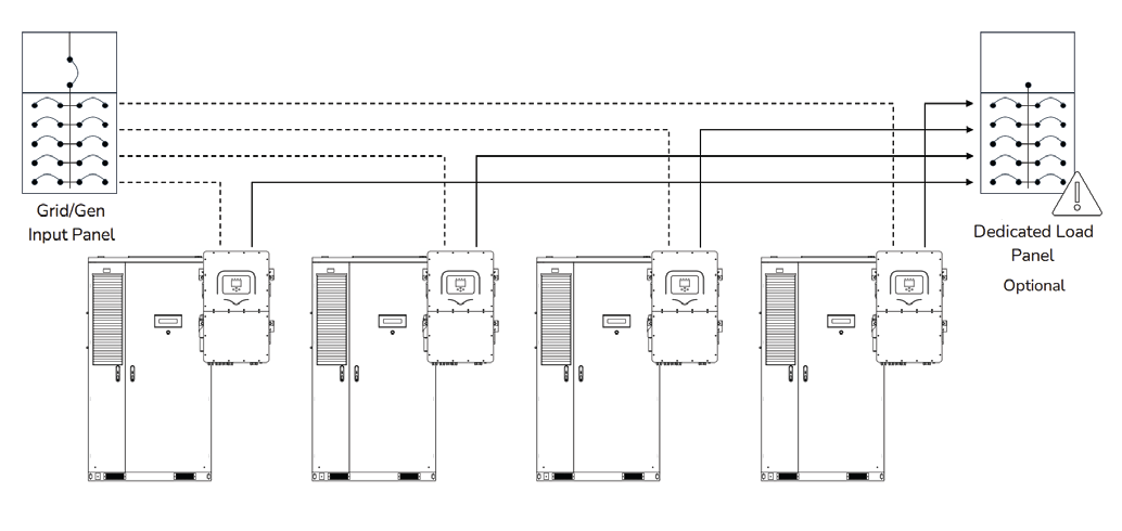
Each AES Cabinet is designed to operate independently and must connect to a dedicated inverter input. Do not combine or parallel the DC outputs of multiple cabinets, as this will result in unbalanced current flow, system instability, and equipment damage.
Parallel Inverters on the AC Bus
System scalability is achieved by paralleling inverters on the AC bus, not by paralleling the batteries. In this design, each inverter has a dedicated battery cabinet, and the inverter AC outputs are synchronized to support larger system loads. This ensures safe, stable, and balanced operation across all components.
Solis S6-EH3P Hybrid inverters offer unlimited scalability on the grid side, allowing the integration of multiple units for high-capacity PV and grid-interactive applications. However, parallel operation on the islanded backup side is limited to ten inverters.
Output of Solis Inverters in Backup
|
Model |
1 Unit |
2 Units |
3 Units |
… |
9 Units |
10 Units |
|---|---|---|---|---|---|---|
|
S6-EH3P30K03-LV-YD-H-US |
72.2 A |
144.4 A |
216.6 A |
… |
649.8 A |
722.0 A |
|
S6-EH3P30K03-NV-YD-H-US |
36.1 A |
72.2 A |
108.3 A |
324.9 A |
361.0 A |
|
|
S6-EH3P40K03-NV-YD-H-US |
48.1 A |
96.2 A |
144.3 A |
432.9 A |
481.0 A |
|
|
S6-EH3P50K03-NV-YD-H-US |
60.1 A |
120.2 A |
180.3 A |
540.9 A |
601.0 A |
|
|
S6-EH3P60K04-NV-YD-H-US |
72.2 A |
144.4 A |
216.6 A |
649.8 A |
722.0 A |
|
NOTE |
|---|
|
For detailed instructions on paralleling multiple units, consult the Solis Commercial Three-Phase HV Hybrid Inverter Manual. |
Compatible Inverter Models and Specifications
|
Inverter Model |
Max Power (PV/AC/Battery) |
|---|---|
|
S6-EH3P30K03-LV-YD-H-US |
60 / 30 / 33 kW |
|
S6-EH3P30K03-NV-YD-H-US |
60 / 30 / 33 kW |
|
S6-EH3P40K03-NV-YD-H-US |
80 / 40 / 44 kW |
|
S6-EH3P50K03-NV-YD-H-US |
100 / 50 / 55 kW |
|
S6-EH3P60K04-NV-YD-H-US |
100 / 60 / 60 kW |
When pairing one AES Cabinet with a single Solis inverter, discharge performance is governed by the inverter's battery input rating, which ranges by model from 33 to 60 kW. The AES Cabinet supports continuous output up to 52 kW, 78 kW, or 104 kW (C/2 rate), so battery performance will scale according to inverter limitations:
|
Inverter Model |
Max Discharge Power |
|---|---|
|
S6-EH3P30K03-LV-YD-H-US |
33 kW |
|
S6-EH3P30K03-NV-YD-H-US |
33 kW |
|
S6-EH3P40K03-NV-YD-H-US |
44 kW |
|
S6-EH3P50K03-NV-YD-H-US |
55 kW |
|
S6-EH3P60K04-NV-YD-H-US |
60 kW |
Systems can be configured with either one battery per inverter or two batteries sharing a single inverter. In all cases, the battery remains within specification. Final system sizing should align with the site’s load profile and desired runtime to ensure optimal performance and value.
Inverter Current and Power Limitation
The Solis S6-EH3P inverter has two battery input terminals, each rated for up to 80 A and a combined maximum of 160 A on the 30-50K models, or 84 A and a combined maximum of 168 A on the 60K model. When paired with the AES CAB-104 (332 Vdc nominal), CAB-160 (499 Vdc nominal), or CAB-210 (665 Vdc nominal), actual current is limited by the inverter’s 33-60 kW power rating, resulting in approximately 25-37.5 A per terminal under regular operation.
Closed-Loop CANbus Connection - LYNK II Gateway
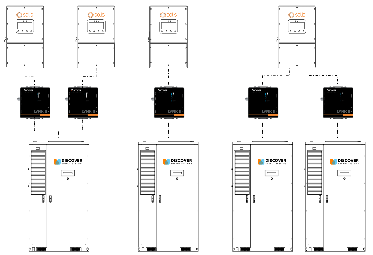
The LYNK II Gateway enables real-time, closed-loop communication between the AES battery cabinet and the Solis inverter. It transmits key battery data such as state of charge, voltage, current, temperature, and operating limits directly to the inverter. This allows the inverter to automatically adjust charging and discharging behavior for safe, efficient, and optimized system performance.
|
NOTICE |
|---|
|
EQUIPMENT DAMAGE
|