
|
NOTE |
|---|
|
For system programming and configuration of parallel inverters, follow the procedure outlined in the inverter manual. |
-
Power On the Inverter. Press the inverter’s power switch. If battery power is present, the inverter will begin its startup process and all five indicator lights will illuminate.
-
Switch On AC and PV Inputs. Turn on the AC grid input breakers and PV input breakers to energise the system.
-
Check for Inverter Activation. If the inverter does not power up, confirm that it is receiving a valid DC input from the battery.
-
Verify Rapid Shutdown (RSD) Status / PV string isolation in accordance with AS/NZS 5033. Ensure the Rapid Shutdown (RSD) switch has not been triggered. When triggered, the inverter will remain off and PV string voltages will stay at a safe level.
-
Keep AC Output Circuits Isolated (if applicable). If the system uses parallel inverter operation or multi-inverter configuration, keep AC output circuits isolated until parallel configuration is complete.
-
Wait for Full Inverter Activation. Allow the inverter to complete its boot sequence before beginning any configuration or system setup.
Inverter Quick Setup Overview
(If there are multiple inverters, repeat this procedure for each inverter.)
When commissioning the inverter for the first time, complete the Quick Setup in the following order:
Inverter Time → Meter Setting → Grid Code → Storage Mode → Battery Model
Inverter Time
Set the current date and time. The default setting will follow your mobile device.
CT / Meter Setting
-
Select CT or Meter (Solis supports Eastron 3-phase, auto-detected meters).
-
Choose the installation location: Grid side (grid connection point), Load side (load connection point), or Grid+PV.
-
Set CT direction: use Forward if the installation is correct; use Reversal if the polarity is reversed.
-
Set CT ratio: default is 60. If using a different CT, adjust manually. If using a meter, set the ratio accordingly.
Grid Code
-
Select the grid code for your region, Australia A, B, or C, or New Zealand. The applicable options are: 4777-A, 4777-B, 4777-C, and 4777-N.
Storage Mode
Choose the system’s energy flow priority:
-
Self-Use, Selling First, or Off-Grid.
|
NOTE |
|---|
|
The load is always the inverter’s priority. Self-use mode makes charging the battery the second priority. Selling First mode makes exporting excess PV power the second priority. Only one mode can be active at a time. |
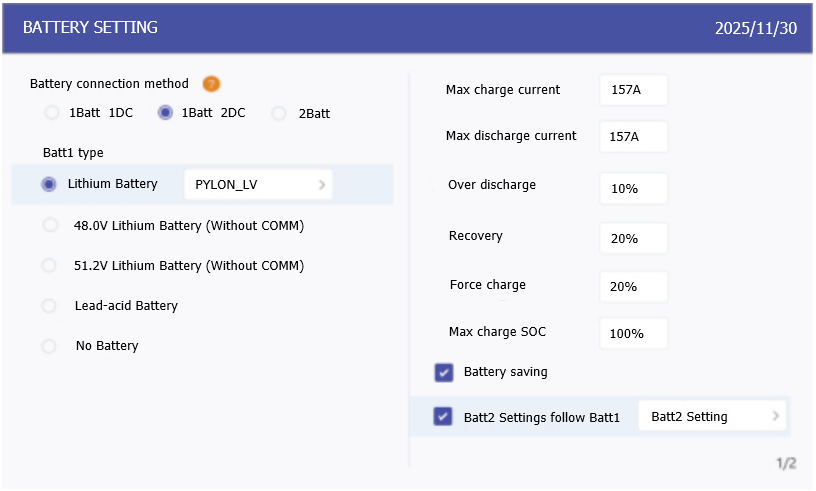
Battery Settings
-
Choose the connection method: 1 Batt 2 DC or 2 Batt 1 DC
-
Select the battery brand and model. If Discover is not listed, choose General_LiBat_HV
-
Set the maximum charge/discharge current: 157 A.
In a two-inverter-to-one-battery configuration, lower the current on each inverter to 39 A. -
For dual-battery systems using the same settings, enable "Batt2 Settings follow Batt1."
Battery Settings Menu
The Battery Settings menu on the inverter interface enables detailed adjustments to battery parameters. Use these settings to fine-tune charging behavior, protect battery health, and optimize system performance.
The table below outlines the recommended configuration values for settings to ensure safe and efficient operation when using the AES battery cabinet. Adjustments may be made based on project-specific requirements.
|
Setting |
Recommended Value |
Notes |
|---|---|---|
|
Max charge current |
157 A |
Matches the battery’s maximum charge capability (Do not exceed cabinet limits). |
|
Max discharge current |
157 A |
Keeps battery within safe continuous discharge range. |
|
Over discharge |
10-20% |
Preserves battery life by avoiding deep discharge. |
|
Recovery |
20-30% |
Set ~10% above over discharge to avoid cycling instability. |
|
Force charge |
10-20% |
Same as Recovery. Only active under grid charge priority conditions. |
|
Max charge SOC |
100% |
Charge to 100% to promote cell balancing in the battery. |
|
NOTE |
|---|
|
Dual Inverter, Single Battery Cabinet Applications
|