
|
|
|---|
|
ELECTRIC SHOCK AND FIRE HAZARD
Failure to follow these instructions may result in death or serious injury. |
Two Sol-Ark Inverters, One AES Battery Cabinet
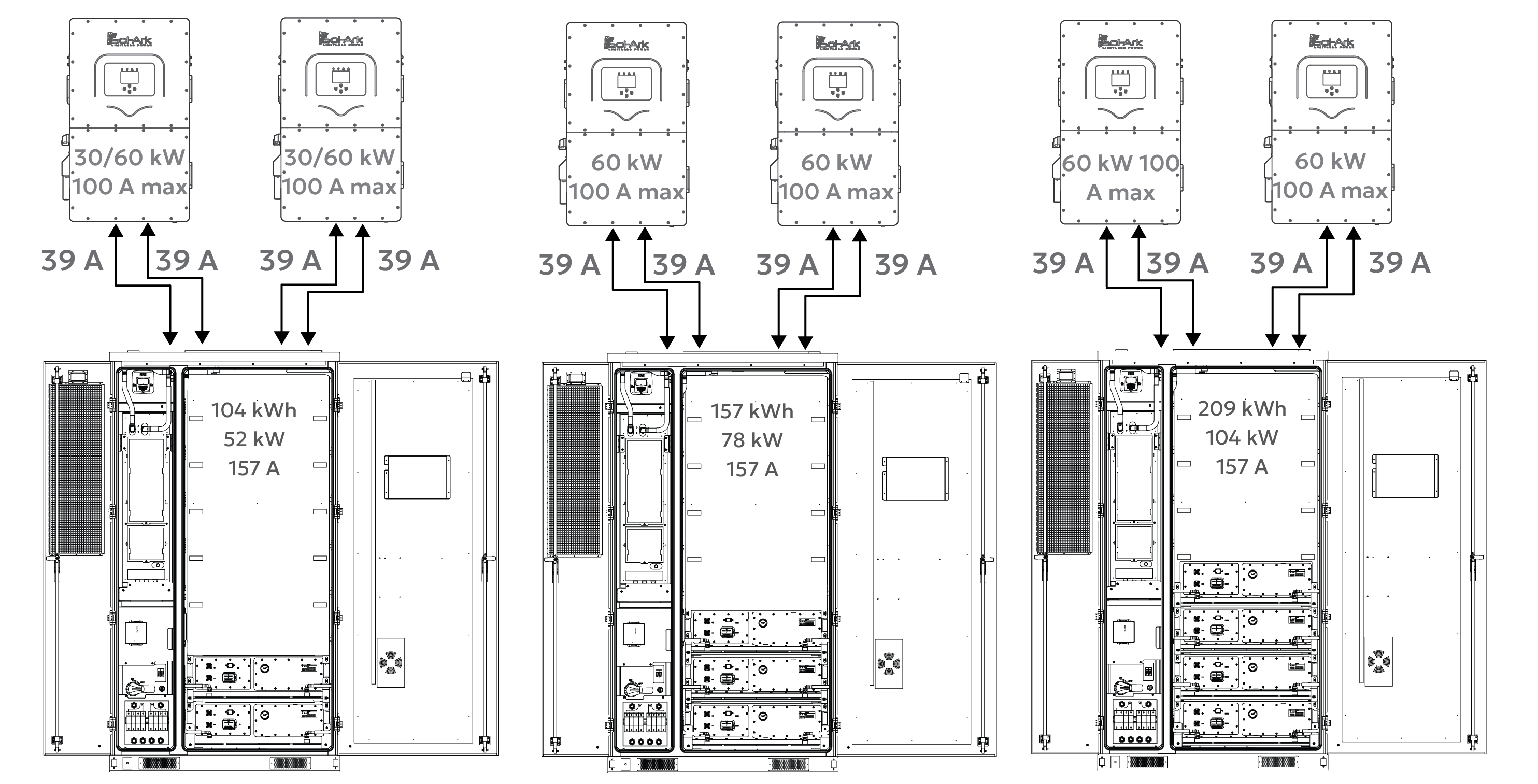
When the AES Cabinet is paired with two Sol-Ark inverters, the AES Cabinet may limit the inverters to a maximum continuous output of 52/104 kW. Actual discharge performance depends on the inverter model’s battery-side power capacity, as shown below.
Full Load Duration (Operation at Max Power)
|
Inverter Model |
Inverter Battery Discharge Limit |
CAB-106 |
CAB-160 |
CAB-210 |
|---|---|---|---|---|
|
AC Output / Usable Storage / Estimated Runtime |
||||
|
30K-3P-208V |
30 kW × 2 = 60 kW |
52 kW* / 104 kWh / 2 hours |
N/A |
N/A |
|
60K-3P-480V |
60 kW × 2 = 120 kW |
52 kW* / 104 kWh / 2 hours |
78 kW* / 157 kWh / 2 hours |
104 kW* / 209 kWh / 2 hours |
* Curtailed by the battery.
These run time estimates assume continuous full-power discharge and operation within safe continuous discharge parameters. Final performance should match the site's energy demand and load profile.
System Scalability - Two Inverters, One AES Cabinet
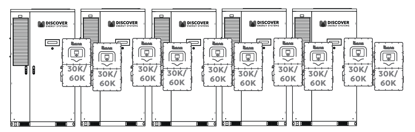
Ten Paralleled Inverters
Two Sol-Ark 30K/60K-3P inverters are paired with each AES battery cabinet.
In this setup:
-
104 to 209 kWh of usable backup energy between two inverters
-
Discharge power is limited by the total inverter capacity or battery power limitation (max 52 to 120 kW)
-
On the backup side, up to ten inverters can be connected in parallel, providing 300-600 kW of continuous backup power and approximately 520-1,045 kWh of total backup energy (5 × 10⁴ kWh / 5 × 209 kWh).
Grid-Tied (Non-Backup) Scalability
The number of inverters or batteries is unlimited for non-backup use. Each inverter runs independently, allowing systems to scale as large as needed for energy shifting, peak shaving, or other grid-interactive applications.
DC Battery Wiring – Two Inverters, One AES Cabinet
Inverter to Cabinet DC Wiring
Each Sol-Ark 3P inverter has two battery input terminals, each rated at 50 A. The AES Cabinet connects to the inverter using:
-
Two positive and two negative #4 AWG conductors to each inverter.
-
Each conductor is protected by a 70 A fuse in the AES Cabinet’s built-in DC distribution box.
This setup ensures balanced current flow to each inverter’s internal DC/DC converter and supports 30-60 kW continuous charge/discharge, depending on the inverter model.
Communication – Two Inverters, One AES Cabinet
Inverter - LYNK II - Cabinet Communication
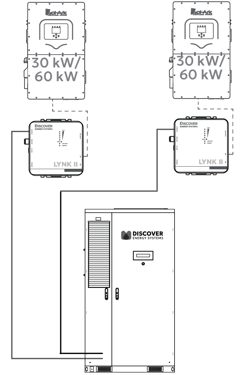
In a two-to-one configuration, a LYNK II Gateway is required for each inverter to enable real-time, managed (closed-loop) control. The AES Cabinet communicates with one Sol-Ark inverter through one LYNK II Gateway (may be included with the battery cabinet), and with a second Sol-Ark inverter through a second LYNK II Gateway.
Wiring
-
Connect one cable from LYNK II #1 CAN port to the Sol-Ark inverter #1’s BMS port. Connect a second cable from LYNK II #1’s LYNK port to the J3 port on the AES Cabinet’s High Voltage Box. On most AES Cabinets, a CAT6 cable is already connected to the J3 port on the AES Cabinet’s High Voltage Box and is accessible from the LYNK II.
-
Connect a third cable from LYNK II #2 CAN port to the Sol-Ark inverter #2’s BMS port. Connect a fourth cable from LYNK II #2’s LYNK port to the J4 port on the AES Cabinet’s High Voltage Box.
|
NOTE |
|
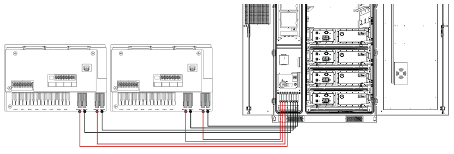
You can use a splitter/combiner, as shown below, to connect two LYNK II Gateways to the J3/J4 ports on the AES Cabinet through a single cable. 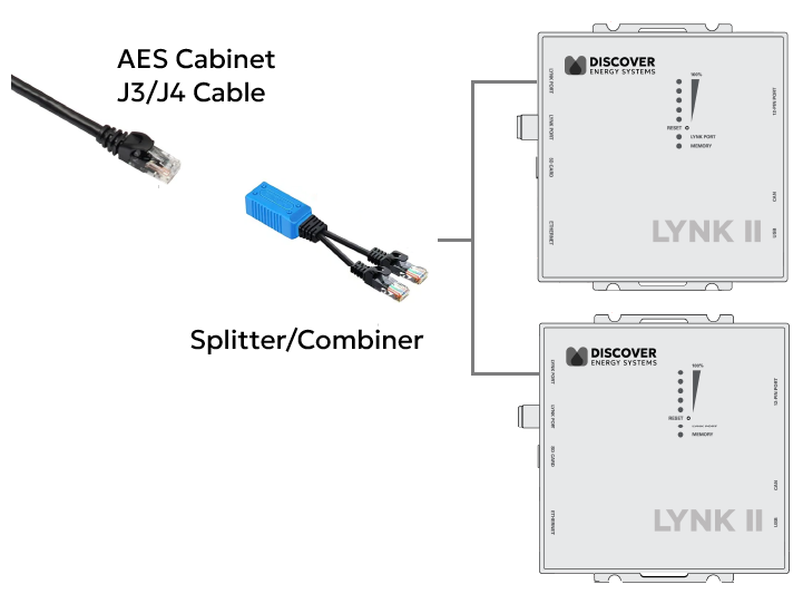
|
Configure LYNK II
-
Start LYNK ACCESS 2.5.0 or later and update both LYNK II Gateways to firmware to 2.5.0 or later.
-
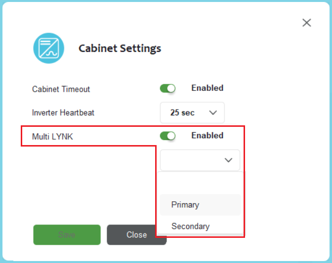
Connect to the first LYNK II device. From the LYNK ACCESS software’s LYNK tab, open the Cabinet Settings tile, enable Multi-LYNK, and set it as Primary.
-
Connect to the second LYNK II device, enable Multi-LYNK and set it as Secondary.
To confirm the system is working correctly, check the battery charging current values on the inverter. If values are 50% of the max, then the 2:1 Multi LYNK configuration is successful.
|
NOTE |
|---|
|
The LYNK II communication link enables the inverter to receive real-time battery data, including state of charge, voltage, current, temperature, and charge/discharge limits, ensuring safe, accurate, and optimized operation.
This setup enables two inverters to manage and monitor the battery cabinet, receiving real-time data for state of charge, voltage, current, temperature, and charge/discharge limits from each LYNK II Gateway. Two independent LYNK II Gateways ensure precise, safe, and optimized performance with dual inverters.