
Each electrical system will have different characteristics and balance-of-system components. Charger settings may require modifications to optimize system performance.
|
NOTICE |
|---|
|
BATTERY DAMAGE
Failure to follow these instructions may result in equipment damage. |
Closed-Loop Charging
Closed-loop charging is a method whereby the battery communicates with a charger and requests a specific charge voltage. Closed-loop charging reduces charge time and increases balancing efficiency compared to open-loop charging.
The HELIOS ESS battery can communicate over a CAT6 or higher cable to support closed-loop charging with the inverters listed in the table in the HELIOS ESS Closed-Loop Communication - Supported Inverters topic. Whether the communication cable is a standard patch cable or requires customized wire pinouts for the RJ45 connectors depends on the inverter manufacturer.
The HELIOS ESS supports closed-loop charging with many other inverter-chargers when combined with the LYNK II Communication Gateway. Refer to the appropriate Application Note available from www.discoverenergysys.com for the set up of closed-loop parameters and integration with specific brands of solar inverter-chargers, solar charger controllers, mobile inverter-chargers, and industrial chargers.
Configure Closed-Loop Charge Settings (LV-BMS)
Dynamic Voltage
The native communication settings on previous models of HELIOS ESS used dynamic voltage to adjust charge settings as it approached a full charge (100% SOC). However, some newer inverters lack accurate tracking of shifting charge voltage (CV) values.
When the inverter’s CC/CV control reacts too slowly or too aggressively to changing voltage targets, it can momentarily drive the DC bus above the requested CV value, triggering over-voltage alarms and unstable charging behavior, even though the battery is operating normally.
For those experiencing these charge issues, you can use LYNK ACCESS 2.5.0 or later and HELIOS ESS firmware 4.10.0 or later to change the charge settings to Dynamic Current.
Change to Dynamic Current
To eliminate overshooting the target voltage, the HELIOS ESS now supports Dynamic Current control, which replaces voltage-based control when operating at a higher SOC. When you use dynamic current control, instead of tracking a shifting CV target, the inverter follows a stable, battery-defined current limit that the inverter can regulate accurately. This removes reliance on the inverter’s CC/CV voltage loop, prevents DC-bus overshoot, and reduces over-voltage alarms.
Configure HELIOS ESS to Use Dynamic Current in LV-BMS
-
Plug your computer into the battery’s USB-C port (or LYNK II Gateway) and open LYNK Access.
-
Update LYNK ACCESS to 2.5 or later.
-
If required, update LYNK II firmware to 2.5 or later.
-
In the Battery tab, update HELIOS firmware to 4.10.0 or later.
Download the latest firmware from the Discover website www.discoverenergysys.com.
-
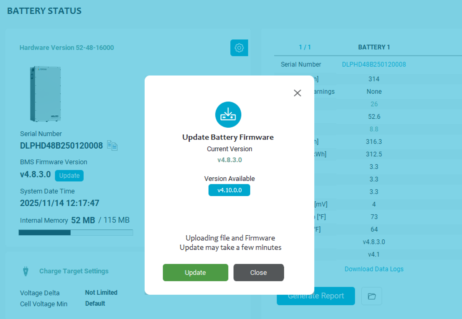
Update Battery Firmware
-
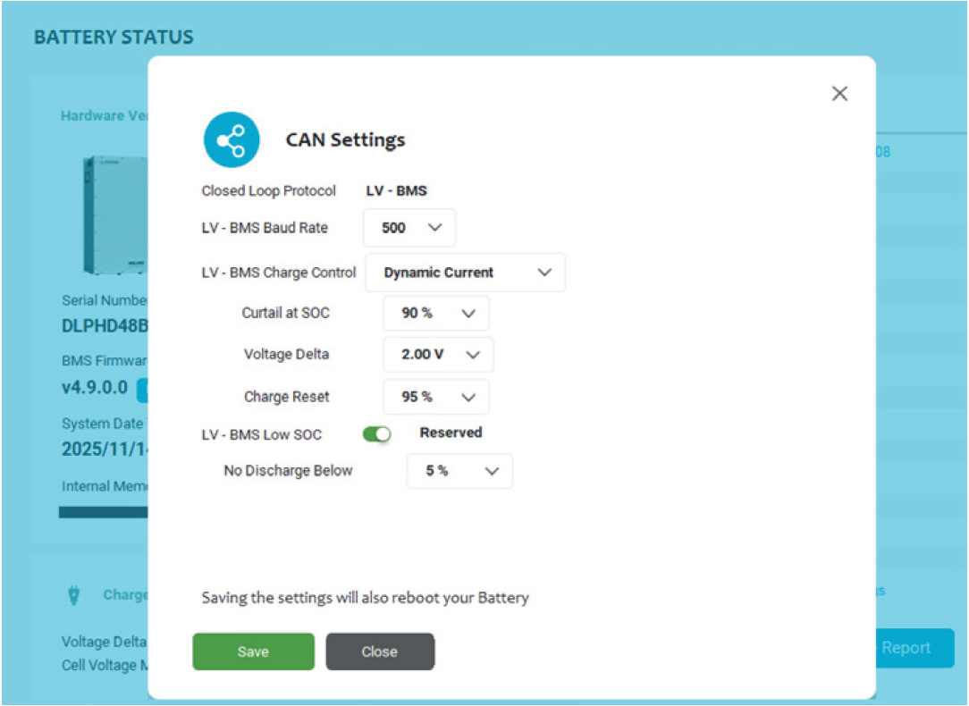
Click the CAN Settings button and set the following.
|
Setting |
Value |
Comments |
|---|---|---|
|
Closed Loop Protocol |
LV-BMS |
You can use this protocol with inverters that support the Pylon protocol, such as Sol-Ark, Victron, Luxpower, Deye, and others. |
|
LV-BMS Baud Rate |
500 |
The default rate of 500 kbps is compatible with most devices. |
|
LV-BMS Charge Control |
Dynamic Current |
The default values for Dynamic Current apply to most applications.
|
|
Curtail at SOC |
90% |
SOC when charging slows down or stops. Use 80-85% for high charge current, and up to 95% for lower charge current. |
|
Voltage Delta |
2.00 V |
Controls how quickly the charge current tapers, based on the difference between the pack voltage and the algorithm’s target voltage (56.0 V).
|
|
Charge Reset |
95% |
Defines the SOC hysteresis used to restart charging after a full charge cycle. The system resumes charging after the battery falls below this SOC threshold, to prevent repeatedly cycling at the top of the charge. |
|
LV-BMS Low SOC |
Reserved |
Creates a charge reserve on the battery to prevent deep discharge events that would otherwise require a manual recovery. |
|
No Discharge Below |
5% |
-
Click Save.
|
NOTE |
|---|
|
If you are using a LYNK II Gateway in your system with an inverter that supports the Pylon protocol, such as Sol-Ark, Victron, Luxpower, Deye, and others, you can use the LV-BMS protocol instead and use the same configuration settings described above. |