
The HELIOS ESS supports closed-loop communication with the GROWATT inverters
listed in the Closed-Loop Communication with Inverters table in the HELIOS ESS Closed-Loop Communication topic.
To enable communication between the inverter and batteries:
-
Connect a CAT6 or higher straight cable from the HELIOS ESS COM2 port to the
BMS port of the GROWATT inverter-charger.
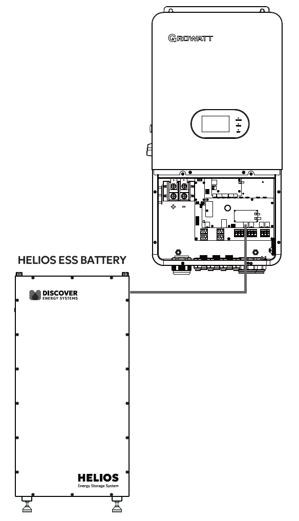
GROWATT CAN Connection
-
Configure the Inverter-Charger
-
Using the touch screen on the inverter-charger, navigate to Main Screen >
Settings > Battery Settings. -
Specify the battery settings according to the instructions in the tables that follow.
-
Touch a field to specify its value.
-
Touch the Up and Down arrows to scroll through the screens.
-
-
Exit and restart the inverter-charger.
|
NOTE |
|---|
|
|
NOTE |
|---|
|
If using multiple inverter-chargers, configure GROWATT inverter-chargers to operate in parallel before setting the battery operation parameters. |
Main Screen > System Setup > Battery Setting
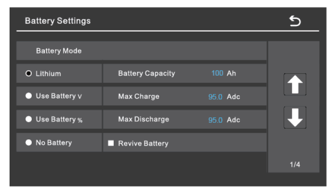
Battery Settings - GROWATT Closed-loop Charge Settings (Page 1)
|
Battery Settings (page 1) |
|
|---|---|
|
Batt Mode |
Select the Lithium option to use the battery BMS. |
|
Refer to the electrical specifications in the battery manual to set the battery, charge, and discharge parameters. |
|
|
Battery Capacity |
Set to the number of Discover Lithium batteries x Ah capacity of each. For example, set to 628 Ah for two HELIOS ESS 52-48-16000 batteries, each rated at 314 Ah capacity. |
|
Max Charge |
Set to the lesser of the inverter’s max charge capacity, or the quantity of attached batteries, multiplied by the battery model’s specific max charge rating. For example, the SPH 10000TL-HU-US inverter would be set to the lessor of the inverter’s max charge rate of 200 A, or 380 A for two HELIOS ESS batteries. NOTE: Each HELIOS ESS battery is rated at a 200 A charge rate, but when connected in parallel, the maximum current is limited by internal busbars. For the recommended maximum current for paralleled HELIOS ESS, refer to Minimum Specifications for Battery Systems. |
|
Max Discharge |
Set to the lesser of the inverter’s max discharge capacity, or the quantity of attached batteries, multiplied by the battery model’s specific max discharge rating. For example, the SPH 10000TL-HU-US inverter would be set to the lessor of the inverter’s max discharge rate of 200 A, or 380 A for two HELIOS ESS 52-48-16000 batteries. NOTE: Each HELIOS ESS battery is rated at a 200 A discharge rate, but when connected in parallel, the maximum current is limited by internal busbars. For the recommended maximum current for paralleled HELIOS ESS, refer to Minimum Specifications for Battery Systems. |
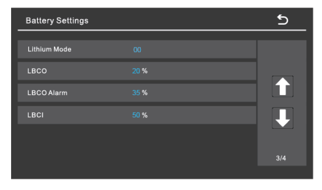
Battery Settings - GROWATT Closed-loop Charge Settings (Page 3)
|
Battery Settings (page 3) |
|
|---|---|
|
Lithium Mode |
Set this value to 00 (Pylon). |
|
LBCO |
Specify the battery SOC at which to stop discharge (low battery cut-off, LBCO), and the SOC at which to allow discharge again (low battery cut-in, LBCI). |
|
LBCO Alarm |
|
|
LBCI |
|
Set other settings to match the user preferences or the particular use case.