
If closed-loop communication cannot be established and you need to resume operation, you may have to manually convert the Noark inverter-charger to an open-loop configuration. Refer to the latest Discover Lithium battery documentation for battery values and the latest NOARK documentation for details on menu navigation and the setup procedure.
Specify the battery settings according to the instructions in the tables that follow
|
NOTE |
|---|
|
Depending on your system and particular use case, there may be other settings that require configuration. Refer to the inverter manual for information on these settings. |
Open-Loop - Battery Setting
Battery Setting - Noark Open-Loop Charge Settings
|
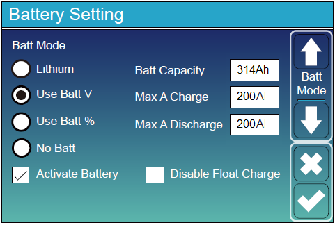
Battery Setting (page 1) |
|
|---|---|
|
Batt Mode |
|
|
Lithium (1)
|
Select the Use Batt V option to use battery voltage for all the settings. |
|
Activate Battery |
Select this check box. |
|
Batt Capacity |
Set to the number of Discover Lithium batteries x Ah capacity of each. For example, set to 628 Ah (2 x 314 Ah) for two HELIOS ESS 52-48-16000. |
|
Max A Charge |
For a single inverter, set to the lesser value between the inverter’s maximum charge rate or the quantity of attached batteries multiplied by the battery’s maximum charge rating. For example: Single phase system with Ex9N-DH-6KS-AU inverter and two HELIOS ESS 52-48-16000 batteries
Three-phase system with three Ex9N-DH-6KT-AU inverters and two HELIOS ESS 52-48-16000 batteries
|
|
Max A Discharge |
For a single inverter, set to the lesser value between the inverter’s maximum discharge rate or the quantity of attached batteries multiplied by the battery’s maximum discharge rating. For example, set the Ex9N-DH-6KS-AU inverter to the lesser of the inverter’s maximum discharge rate of 135 A, or 380 A for two HELIOS ESS 52-48-16000 batteries.
For a three-phase system, set to the lesser value between the master inverter’s maximum discharge rate or the quantity of attached batteries multiplied by the battery’s maximum discharge rating divided by the number of inverters. For example, set the Ex9N-DH-6KT-AU inverter to the lesser of the inverter’s maximum discharge rate of 150 A, or 133 A for two HELIOS ESS 52-48-16000 batteries that are each rated at a maximum discharge rate of 200 A and then divided by 3 inverters (2 x 200 A ÷ 3 = 133.33 A). |
(1) To configure the open-loop parameters, do not select the Lithium parameter. Selecting the Lithium parameter enables the BMS for closed-loop communication.
Battery Setting (Page 3)
Battery Setting - Noark Inverter Shutdown/Restart Settings
|
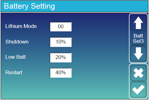
Battery Setting (page 3) |
|
|---|---|
|
Lithium Mode |
This property is not applicable in an open-loop configuration. |
|
Shutdown |
Turns off the inverter when the battery reaches this SOC. |
|
Low Batt |
Inverter outputs a warning when the battery reaches this SOC. |
|
Restart |
Inverter AC output continues when the battery reaches this SOC. |
Battery Setting - Noark Open-loop Battery Settings
|
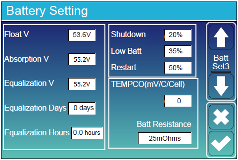
Battery Setting (page 3) |
|
|---|---|
|
Float V |
53.6 V |
|
Absorption V |
55.2 V |
|
Equalization V |
Do not equalize Discover Lithium batteries |
|
Equalization Days |
|
|
Equalization Hours |
|
|
Shutdown (%) |
Turns off the inverter when the battery reaches the specified SOC. |
|
Low Batt (%) |
Inverter outputs a warning when the battery reaches the specified SOC. |
|
Restart (%) |
Inverter AC output continues when the battery reaches the specified SOC. |
|
TEMPCO (mv/C/Cell) |
Set to 0 mv/C/Cell. (1) |
|
Batt Resistance |
Keep the default value of 25 mOhms. |
(1) Discover Lithium batteries do not require temperature compensation. Setting TEMPCO to 0 mv/C/Cell disables inverter controlled temperature compensation.
|
NOTE |
|---|
|
For more information about configuring the GROWATT inverter-charger, refer to product documentation on Noark website (na.noark-electric.com) or the LYNK II Installation and User Manual (805-0033). |