
Schneider Electric Inverter Configuration (Closed Loop Without LYNK II)
NOTICE |
|---|
EQUIPMENT DAMAGE When operating in a closed loop, the BMS communicates the internal battery temperature with Schneider Electric devices. Remove any temperature sensors from inverters or charge controllers so they do not override or conflict with the BMS. Failure to follow these instructions may result in equipment damage. |
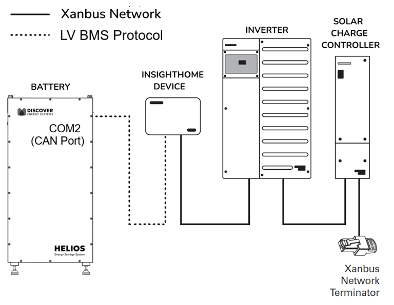
The HELIOS ESS supports closed-loop communication with the Schneider Electric XW PRO inverter-chargers listed in the Closed-Loop Communication with Inverters table in the HELIOS ESS Closed-Loop Communication topic.
To enable communication between the inverter and batteries:
Connect a CAT6 or higher straight cable to the HELIOS ESS COM2 port, split the wires, and connect them to the corresponding CAN pins on the Insight device.
Wiring
This describes how to wire the HELIOS ESS COM2 (CAN Port) to the Schneider Electric Insight device.
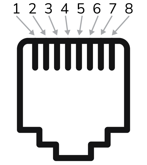
HELIOS ESS CAN Port Pin Map
PIN | DESCRIPTION |
|---|---|
1 | — |
2 | — |
3 | — |
4 | CAN Low |
5 | CAN High |
6 | Ground |
7 | (brown and white striped wire) |
8 | (brown colored wire) |
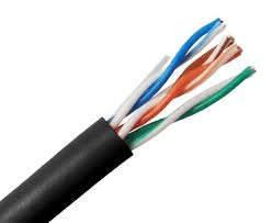
Use a CAT6 or higher cable to connect the pins on the HELIOS ESS CAN port to the CAN pins of either the 12-pin connector of InsightHome or the 26-pin connector of InsightFacility.
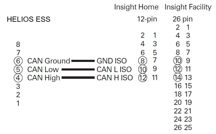
Mapping HELIOS ESS CAN Port Pins to Insight Device Pins
Top Row |
| Bottom Row | ||
|---|---|---|---|---|
1 | Digital Output (0-40 Vdc) | 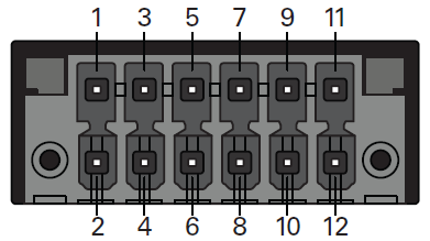 InsightHome 12-pin connector | 2 | Digital Input 1 (12 Vdc) |
3 | GND | 4 | Digital input 2 (12 Vdc) | |
5 | Do not connect | 6 | Do not connect | |
7 | GND ISO | 8 | GND ISO | |
9 | RS485 A ISO | 10 | CAN L ISO | |
11 | RS485 B ISO | 12 | CAN H ISO | |
Top Row |
| Bottom Row | ||
|---|---|---|---|---|
1 | GND | 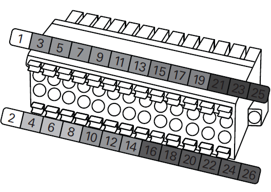 InsightFacility 26-pin connector | 2 | 9-24 Vdc power input |
3 | 0-10 Vdc analog input 1 | 4 | GND | |
5 | 0-10 Vdc analog input 2 | 6 | 12 Vdc digital input 1 | |
7 | GND | 8 | 12 Vdc digital input 2 | |
9 | 4-20 mA input 1 | 10 | ISO1 CAN GND | |
11 | 4-20 mA input 2 | 12 | ISO1 CAN L | |
13 | GND | 14 | ISO1 CAN H | |
15 | Relay 1 N/O | 16 | ISO2 RS485 GND | |
17 | Relay 1 COM | 18 | ISO2 RS485 1A | |
19 | Relay 1 N/C | 20 | ISO2 RS485 1B | |
21 | Relay 2 N/O | 22 | ISO2 RS485 GND | |
23 | Relay 2 COM | 24 | ISO2 RS485 2A | |
25 | Relay 2 N/C | 26 | ISO2 RS485 2B | |
Using your computer, log in to the InsightHome or InstightFacility device and configure the parameters for Schneider Electric devices.
Specify settings according to the following instructions.
Setting up the Insight Device
Updating Schneider Device Firmware
Ensure that all devices have up-to-date firmware.
Update the firmware of the InsightHome or InsightFacility.
Setup > Configuration
From Firmware Upgrade, click Upload Package and install the latest firmware file.
Update the firmware of the XW PRO.
Devices > Inverter/Chargers > Firmware
Click Upgrade and install the latest firmware file.
Update the firmware of the MPPT controller.
Devices > Charge Controllers > Firmware
Click Upgrade and install the latest firmware file.
Setting the Insight Device to use BMS Configuration
Set up InsightHome or InsightFacility to use the BMS Configuration with InsightLocal.
This setup menu automatically configures the XW PRO according to the selected battery model and the number of batteries in the system. It also configures the XW PRO’s Charge Cycle to External BMS, the Battery Type to Li-ion, and SOC Control to Enabled. MPPT Solar Charge Controllers connected to the system will also be automatically configured with the correct charge voltage.
NOTE |
|---|
|
> Device Association
InsightLocal > BMS > Configuration (Advanced) > Device Identification
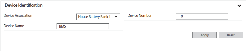
From the Device Association drop-down menu, select the appropriate battery.
Click APPLY.
NOTE |
|---|
Complete the Device Association before continuing with BMS Setup. |
> BMS Setup
InsightLocal > Setup > BMS Setup
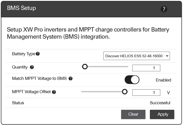
InsightLocal > BMS Setup | System Value |
|---|---|
Battery Type | Select the appropriate Discover Lithium battery model. NOTE:
|
Quantity | Specify the number of lithium batteries |
Match MPPT Voltage to BMS | Set to ENABLED |
MPPT Voltage Offset | Set to 1.0 V. Adjust if batteries do not fully charge or the battery’s overvoltage protection is engaged. Lowering this value brings the charge controller’s tolerance for the inverter voltage delta closer. For example, 1 V means the charge controller operates at 1 V less than the readings on the inverter. |
Verify Battery Network Connections
Review the following steps to verify that all batteries communicate with the LYNK II Gateway and the Schneider system.
Devices > Inverter/Chargers > Configuration (Advanced) > Battery Settings
If the connection was successful, the listed Battery Bank Capacity is as follows:
Battery Settings | HELIOS ESS (52-48-16000) |
|---|---|
Battery Bank Capacity | 314 Ah × number of batteries |
If the connection is unsuccessful, check that the Discover LYNK/AEbus network is correctly terminated and that there is no damage to the network cabling, terminators, and connectors. Confirm all batteries have the same firmware revision. Rectify any problems and verify again.
NOTE |
|---|
Discover batteries are visually represented by a Conext Battery Monitor image when viewed on InsightLocal or InsightCloud. |