
If closed-loop communication cannot be established and you need to resume operation, you may have to convert the Sol-Ark inverter to an open-loop configuration manually. Refer to the latest Discover Energy Systems documentation for battery values and the latest Sol-Ark documentation for menu navigation and details on the setup procedure.
|
NOTE |
|---|
|
-
Set the Discover Lithium batteries to ON and set the inverter-charger to ON.
-
Using the touch screen and keypad on the inverter, navigate to System Setup > Battery Setup.
-
Specify the battery settings according to the instructions in the tables that follow. Touch the Up and Down arrows to scroll through screens.
-
Touch the check mark button to save changes.
-
Exit and restart the inverter-charger.
Open Loop: System Setup > Battery Setup > Batt
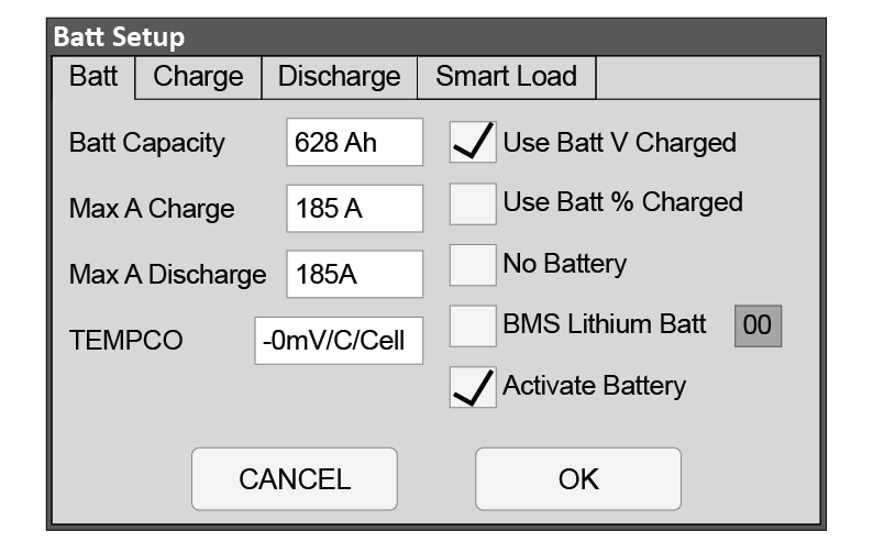
Battery Setting - Sol-Ark Open-Loop Charge Settings
|
Batt Setup > Batt |
|
|---|---|
|
Batt Capacity |
Set to the number of Discover Lithium batteries x Ah capacity of each. For example, set to 628 Ah for two HELIOS ESS 52-48-16000 batteries, each rated 314 Ah capacity. |
|
Max A Charge |
For a single inverter, set to the lesser of the inverter’s maximum charge rate or the quantity of attached batteries multiplied by the battery’s maximum charge rating. For example: Single phase system with 12K-2P-N inverter and two HELIOS ESS 52-48-16000 batteries
Three-phase system with three Sol-Ark 15K-2P-N inverters and two HELIOS ESS 52-48-16000 batteries
|
|
Max A Discharge |
For a single inverter, set to the lesser value between the inverter’s maximum discharge rate or the quantity of attached batteries multiplied by the battery’s maximum discharge rating. For example, set the 12K-2P-N inverter to the lesser of the inverter’s maximum discharge rate of 185 A, or 380 A for two HELIOS ESS 52-48-16000 batteries.
For a three-phase system, set to the lesser value between the master inverter’s maximum discharge rate or the quantity of attached batteries multiplied by the battery’s maximum discharge rating divided by the number of inverters. For example, set the 12K-2P-N inverter to the lesser of the inverter’s maximum discharge rate of 185 A, or 133 A for two HELIOS ESS 52-48-16000 batteries that are each rated at a maximum discharge rate of 200 A and then divided by 3 inverters (2 x 200 A ÷ 3 = 133.33 A). |
|
TEMPCO |
Set to 0 mv/C/Cell. Discover Lithium batteries do not require temperature compensation. |
|
Use Batt V Charged |
Enable |
|
Use Batt % Charged |
Disable |
|
BMS Lithium Batt |
Disable |
|
Activate Battery |
Enable |
Open Loop: System Setup > Battery Setup > Charge
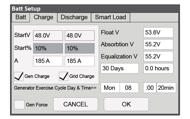
Battery Setting - Sol-Ark Open-loop Battery Settings
|
Batt Setup > Charge |
|
|---|---|
|
StartV |
Set to user preference based on battery voltage. The recommended minimum is 48 V. |
|
Start% |
Unavailable (Grey) in an open-loop configuration. |
|
Float V |
53.6 V |
|
Absorption V |
55.2 V |
|
Equalization V |
Do not equalize Discover Lithium batteries. |
|
Equalization Days |
|
|
Equalization Hours |
|
Open Loop: System Setup > Battery Setup > Discharge
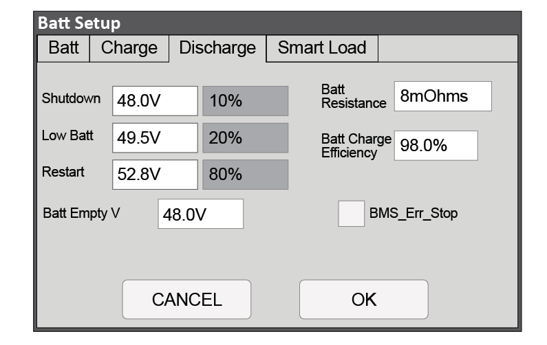
Battery Setting - Sol-Ark Open-loop Battery Settings
|
Batt Setup > Discharge |
|
|---|---|
|
Shutdown |
Adjust values to support the use case or keep the original values. |
|
Low Batt |
|
|
Restart |
|
|
Batt Empty V |
48 V |
|
Batt Resistance |
Set to: 10 mOhm divided by the number of batteries (plus the mOhm value for cable resistance, if known). |
|
Batt Charge Efficiency |
98% |
|
BMS_Err_Stop |
Clear this check box in an open-loop configuration. |
|
NOTE |
|---|
|
For more information about configuring the Sol-Ark inverter-charger, refer to product documentation on Sol-Ark website (sol-ark.com) or the LYNK II Installation and User Manual (805-0033). |