
The HELIOS ESS supports closed-loop communication with the Sol-Ark inverters listed in the Closed-Loop Communication with Inverters table in the HELIOS ESS Closed-Loop Communication topic.
To enable communication between the inverter and batteries:
-
When setting up closed-loop communication with:
-
5K-1P, 6K-1P, 8K-1P, 10K-1P, 5K-2P, 8K-2P, 8K-2P-L, 12K-2P, 15K-2P, and 18K-2P outdoor inverters, connect a CAT6 or higher straight cable from the HELIOS ESS COM2 port to the CAN port of the Sol-Ark inverter-charger.
-
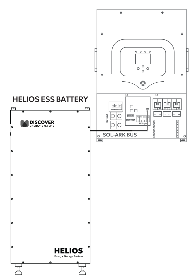
Sol-Ark Outdoor 5K-1P / 5K-2P / 8K-P2 / 12K-P2 / 15K-P2 / 18K-P2
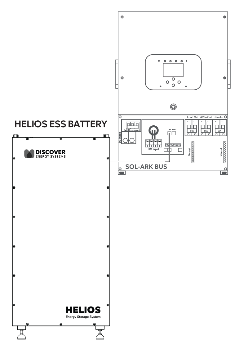
(Legacy) Indoor Sol-Ark 12K Hybrid
-
Legacy) 8K to 12K Hybrid Indoor inverters, create your own cable as identified in Cables for Closed-Loop Communication Without LYNK II - Legacy Sol-Ark, and connect the cable from the HELIOS ESS COM2 port to the CAN port of the Sol-Ark inverter-charger.
-
Configure the inverter-charger.
-
Using the touch screen and keypad on the inverter-charger, navigate to System Setup > Batt Setup.
-
Specify the settings according to the instructions in the tables that follow to stop power conversion when a closed-loop communication error occurs.
-
Touch the Up and Down arrows to scroll through the screens. Touch the checkmark button to save changes.
-
-
Exit and restart the inverter-charger.
|
NOTE |
|---|
|
|
NOTE |
|---|
|
Depending on your system and particular use case, there may be other settings that require configuration. Refer to the inverter manual for information on these settings. |
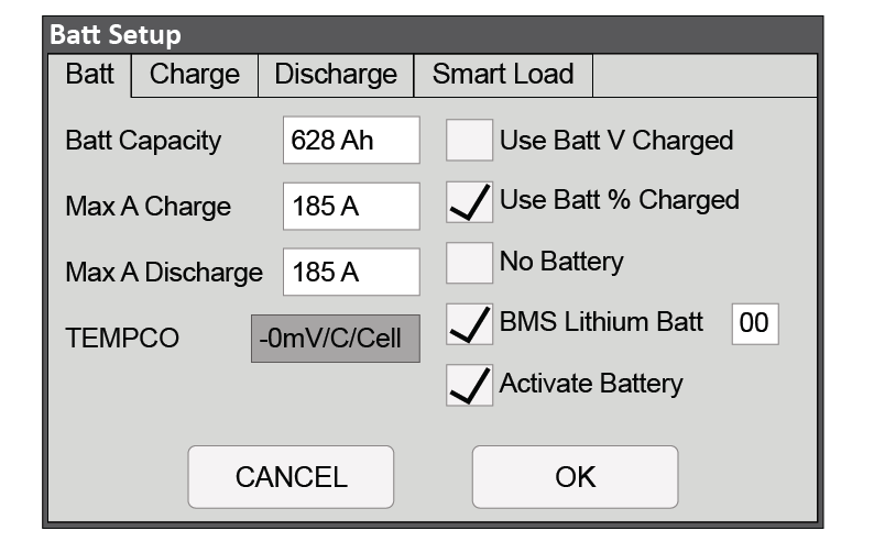
System Setup > Batt Setup > Batt
Battery Setting - Sol-Ark Closed-loop Charge Settings
|
Batt Setup > Batt |
|
|---|---|
|
Batt Capacity |
Set to the number of Discover Lithium batteries x Ah capacity of each. For example, set to 628 Ah for two HELIOS ESS 52-48-16000 batteries, each rated 314 Ah capacity. |
|
Max A Charge |
For a single inverter, set to the lesser of the inverter’s maximum charge rate or the quantity of attached batteries multiplied by the battery’s maximum charge rating. For example: Single phase system with 12K-2P-N inverter and two HELIOS ESS 52-48-16000 batteries
Three-phase system with three Sol-Ark 15K-2P-N inverters and two HELIOS ESS 52-48-16000 batteries
|
|
Max A Discharge |
For a single inverter, set to the lesser value between the inverter’s maximum discharge rate or the quantity of attached batteries multiplied by the battery’s maximum discharge rating. For example, set the 12K-2P-N inverter to the lesser of the inverter’s maximum discharge rate of 185 A, or 380 A for two HELIOS ESS 52-48-16000 batteries.
For a three-phase system, set to the lesser value between the master inverter’s maximum discharge rate or the quantity of attached batteries multiplied by the battery’s maximum discharge rating divided by the number of inverters. For example, set the 12K-2P-N inverter to the lesser of the inverter’s maximum discharge rate of 185 A, or 133 A for two HELIOS ESS 52-48-16000 batteries that are each rated at a maximum discharge rate of 200 A and then divided by 3 inverters (2 x 200 A ÷ 3 = 133.33 A). |
|
TEMPCO |
This field is disabled when the BMS Lithium Batt check box is selected. |
|
Use Batt V Charged |
Disable |
|
Use Batt % Charged |
Enable |
|
BMS Lithium Batt |
Enable and set the value to 00. (2) |
|
Activate Battery |
Enable |
(1) The recommended value for Max A Charge is 75% of the rated maximum charge current for the battery.
(2) Selecting the BMS Lithium Batt check box confirms closed-loop operation. The value 00 specifies the CANBus Battery mode (Pylon).
System Setup > Batt Setup > Charge
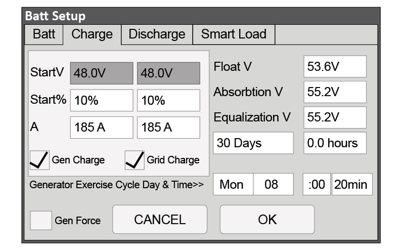
Battery Setting - Sol-Ark Closed-Loop Charge Settings
|
Batt Setup > Charge |
|
|---|---|
|
StartV |
Unavailable (Grey) in a closed-loop configuration. |
|
Start% |
Set to user preference based on battery State-Of-Charge as a percentage. The recommended minimum is 10%. |
System Setup > Batt Setup > Discharge
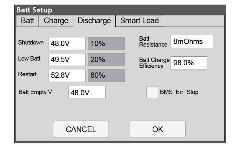
Advanced Function - Sol-Ark Closed-Loop Setting
|
Batt Setup > Discharge |
|
|---|---|
|
Shutdown |
Adjust values to support the use case or keep the original values. (1) |
|
Low Batt |
|
|
Restart |
|
|
Batt Empty V |
48 V |
|
Batt Resistance |
Set to: 10 mOhm divided by the number of batteries (plus the mOhm value for cable resistance, if known). (2) |
|
Batt Charge Efficiency |
98% |
|
BMS_Err_Stop |
Selecting this check box is recommended. A check mark causes the inverter-charger to stop operating if there is a communication error with the battery BMS. |
(1) A closed-loop configuration uses % state-of-charge. Voltage values are not configurable.
(2) This value should include cable and connection resistance. The formula provided is to help calculate a general value.
(3) BMS_Err_Stop MUST be enabled to cause the inverter to stop operating if there is a communication error. If BMS_Err_Stop is disabled, the inverter will continue to operate using the last communicated battery values.