
DE-ENERGIZED SYSTEM INSPECTION
|
|---|
ELECTRICAL HAZARD
Failure to follow these instructions may result in death or serious injury. |
Cabinet ID: |
|
Technician: |
|
Date: |
|
External Visual Inspection
Task | Pass/Fail | Notes |
|---|---|---|
Confirm there is no deformation, scratches, rust, other defects in appearance | ☐ / ☐ | |
Confirm there is no abnormality at welded seams, no peeling of paint, bubbles, and the color is consistent.
| ☐ / ☐ |
Internal Visual Inspection
✅ Fire Suppression System
Task | Pass/Fail | Notes |
|---|---|---|
Confirm the smoke sensor, temperature sensor, and fire extinguishing device (Aerosol) are mounted securely and the tightening marks drawn with a marker for the screws have not shifted.
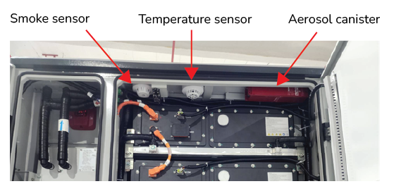 Fire Suppression System | ☐ / ☐ |
✅ Cable Connections
Task | Pass/Fail | Notes |
|---|---|---|
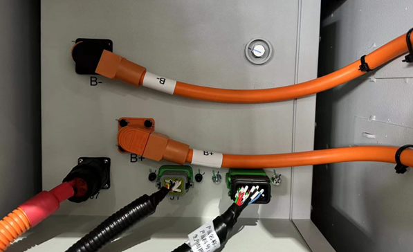
Check that the DC cables are properly connected.
 DC cable connections | ☐ / ☐ | |
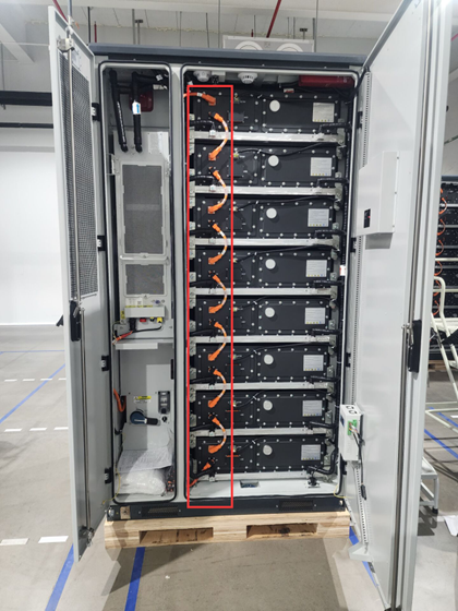
Check that the communication cables are properly connected.
 Communication Cable Connections | ☐ / ☐ |
|
Check that the auxiliary power cables are properly connected.
 Auxiliary Power Cable Connections | ☐ / ☐ |
|
✅ Manual Service Disconnect (MSD)
Task | Pass/Fail | Notes |
|---|---|---|
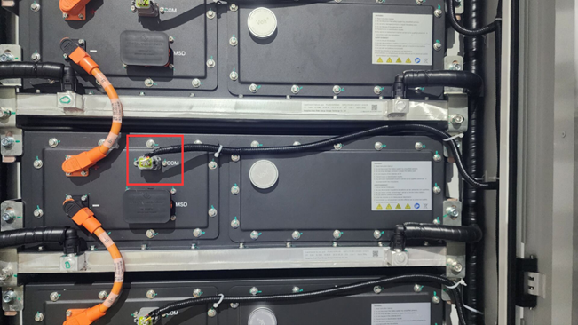
Visually inspect the MSD (Manual Service Disconnect) of each battery pack. 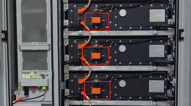
| ☐ / ☐ |
|
✅ Insulation test
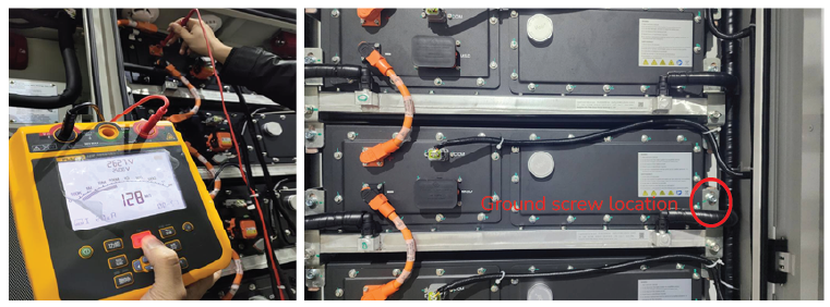
Insulation Testing
Task | Pass/Fail | Notes |
|---|---|---|
Check the positive insulation resistance value
| ☐ / ☐ | |
Check the negative insulation resistance value
| ☐ / ☐ |
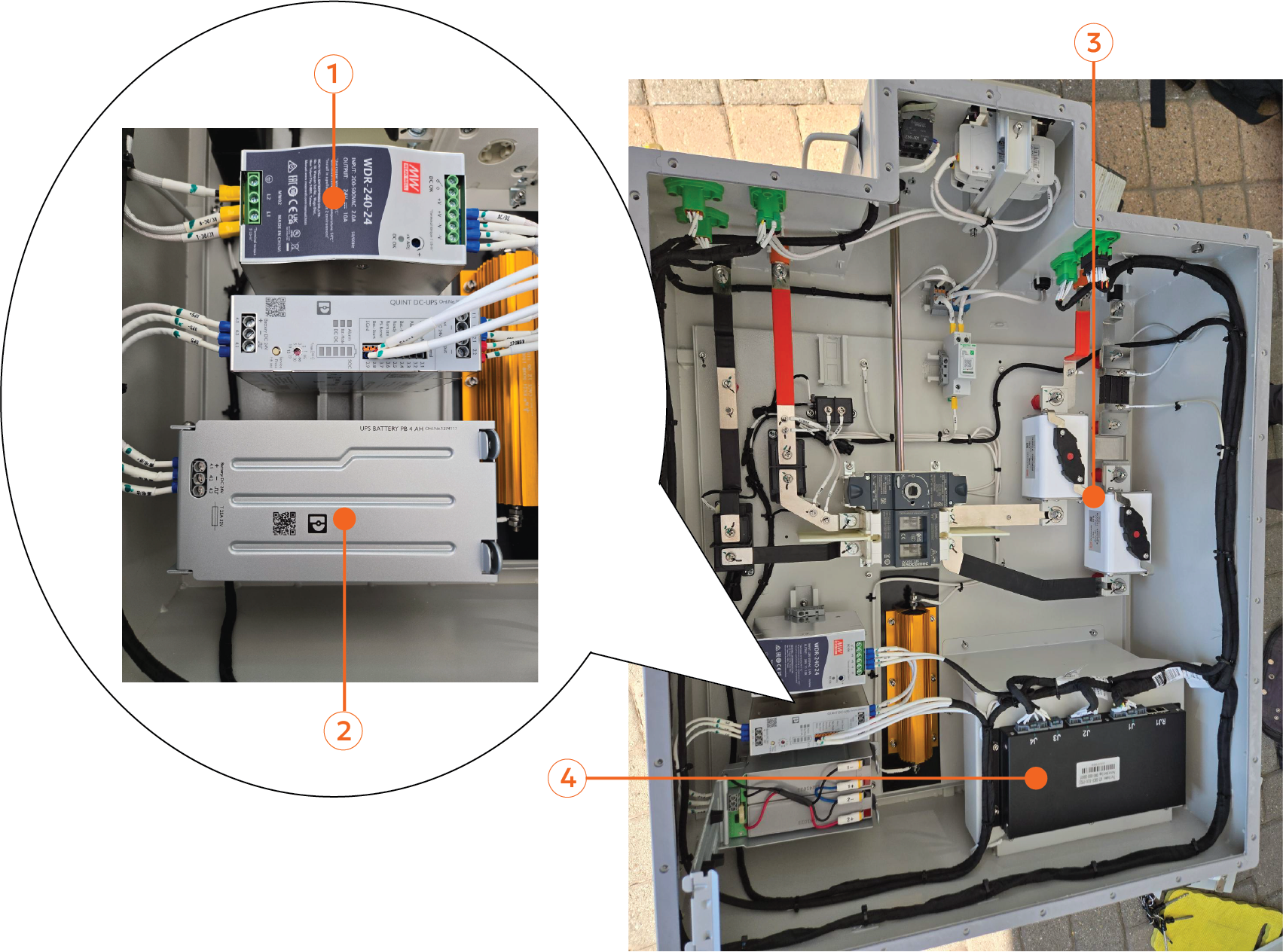
✅ High Voltage Box
Task | Pass/Fail | Notes |
|---|---|---|
Inspect the HVB for physical damage, corrosion, deformation, and signs of overheating. | ☐ / ☐ | |
Confirm all cables are securely fastened. | ☐ / ☐ |
NOTE |
|---|
Remove and inspect the High Voltage Box every 5 years, only when replacing the UPS battery. |
Power Supplies
UPS Battery
350 A Fuses
BCU
Task | Pass/Fail | Notes |
|---|---|---|
| ☐ / ☐ | |
| ☐ / ☐ |