
The Thermal Management System (TMS) regulates the temperature of battery cells in the AES Cabinet.
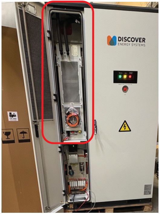
Thermal Management System (TMS)
|
|
TMS System Design
-
Liquid Cooling Loop: Closed-loop glycol-water mix (50:50) with variable-speed pump.
-
Refrigeration Circuit: R-513A refrigerant compressor that provides ≥8 kW cooling capacity at 45°C (113°F) ambient temperatures.
-
Heating Elements: PTC resistive heaters (≥2.5 kW) for cold-weather operation.
-
Integrated Controls: Each cabinet uses a Battery Control Unit (BCU) and Battery Monitoring Units (BMUs) for real-time regulation.
-
Sensors: Multiple NTC thermistors at pack and cell level.