
Design and Features
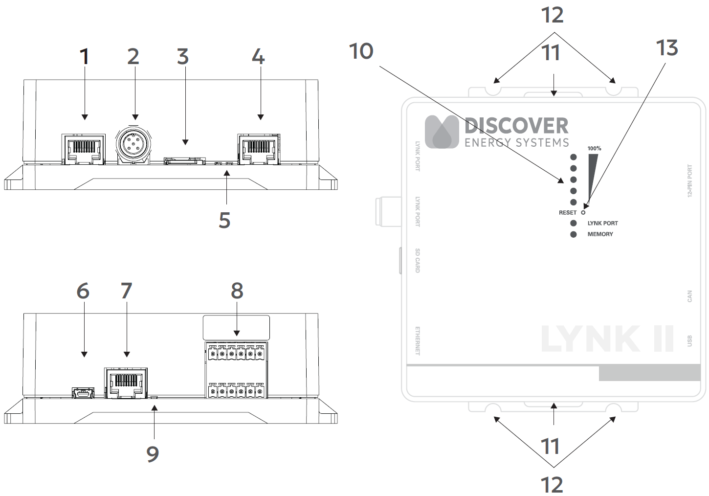
Ports, Buttons, LEDs, and Mounting Hold Downs
NAME | DESCRIPTION | |
|---|---|---|
1 | LYNK Port (AEbus) | RJ45 connection for LYNK Network communication input. Termination is configurable. (Terminated by Default) |
2 | IEC M12 5-pin connector for LYNK Network communication input. Termination is configurable. (Terminated by Default) | |
3 | Mini SD Card Slot | Used for extended battery data logging (128 GB) and updating battery and LYNK II device firmware. |
4 | Ethernet Port | Used for LYNK CLOUD communication. |
5 | Indicates communication activity. | |
6 | USB Mini Port | USB device port to connect with LYNK ACCESS software on Windows 10 / 11. |
7 | CAN Out | RJ45 connection used for CAN communications. Termination is configurable. |
8 | Connections are used by the relays, CAN Out, and supply power. | |
9 | Indicates communication activity. | |
10 | Five LEDs indicate the State-of-Charge level. LYNK Port LED indicates the status and activity on the LYNK Port (RJ45 or 5-pin DIN connector). Memory LED indicates SD Card status. | |
11 | Hold-Down Points | Hold-down points for mounting the device with straps. |
12 | Mounting Slots | Slots for mounting the device with screws or bolts. |
13 | Pinhole button that you press to reset the LYNK II. |