
|
NOTE |
|---|
|
For system programming and configuration of parallel inverters, follow the procedure in the Sol-Ark 30K-3P-208V or 60K-3P-480V C&I Installation Guide and User Manual. |
-
Power On the Inverter. Press the inverter’s power switch. If battery power is present, the inverter will begin its startup process and all five indicator lights will illuminate.
-
Switch On AC and PV Inputs. Turn on the AC grid input breakers and PV input breakers to energize the system.
-
Check for Inverter Activation. If the inverter does not power up, confirm that it is receiving a valid DC input from the battery.
-
Verify Rapid Shutdown (RSD) Status. Ensure the Rapid Shutdown (RSD) switch has not been triggered. If triggered, the inverter will remain off and PV string voltages will stay at a safe level.
-
Keep AC Output Circuits Isolated (if applicable). If the system uses inverter stacking or multi-inverter configuration, keep AC output circuits isolated until stacking configuration is complete.
-
Wait for Full Inverter Activation. Allow the inverter to complete its boot sequence before beginning any configuration or system setup.
Battery Setup Configuration
If there are multiple inverters, repeat this procedure for each inverter.
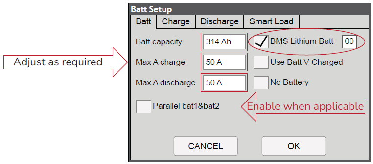
Access the inverter’s System Setup menu, navigate to the Battery Setup, and in the Batt tab configure the inverter communication with the battery, charge and discharge parameters, and parallel operation of the inverter’s DC/DC Converters.
-
From the System Setup menu, select Battery Setup.
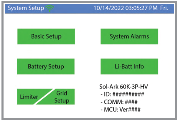
System Setup Menu
-
In the Batt Setup dialog box, open the Batt tab and configure the following.
Batt Setup - Batt Tab
|
NOTE |
|---|
|
Example settings for various system configurations are provided below. |
-
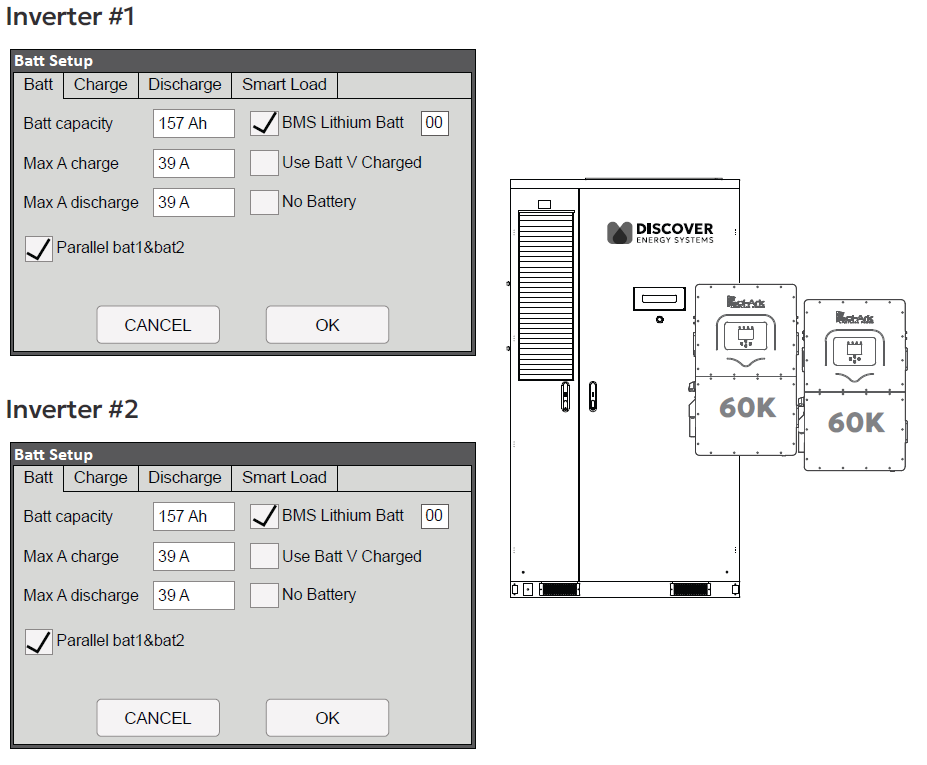
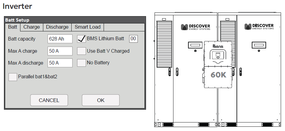
Batt Capacity. Set the battery capacity to match the AES Cabinet usable capacity. For example, 157 Ah if split between two inverters, 314 Ah for one battery and one inverter, or 628 Ah for two cabinets with one inverter.ͬ
-
BMS Lithium Batt. Select this check box for closed communication with the AES Cabinet. Configure the protocol to 00.ͬ
-
MAX A Charge/Discharge. Define the maximum current allowed for charging and discharging the cabinet through the inverter’s DC/DC terminals.ͬ
-
Parallel Bat1&Bat2. Select this check box for applications where both of the inverter’s DC Battery Connections are to a single cabinet and the communication cable is connected only to the inverter’s BMS1 port. The inverter will use both integrated Battery DC/DC converters in parallel, providing the full current to each input/output between the inverter and the cabinet.
-
Configure the Inverter’s charge and discharge limits based on the system configuration. Refer to the examples below.
|
NOTE |
|---|
|
Before changing tabs, always click OK to save the settings. After clicking OK, you must navigate back to the respective settings menu each time. |
Example Configurations
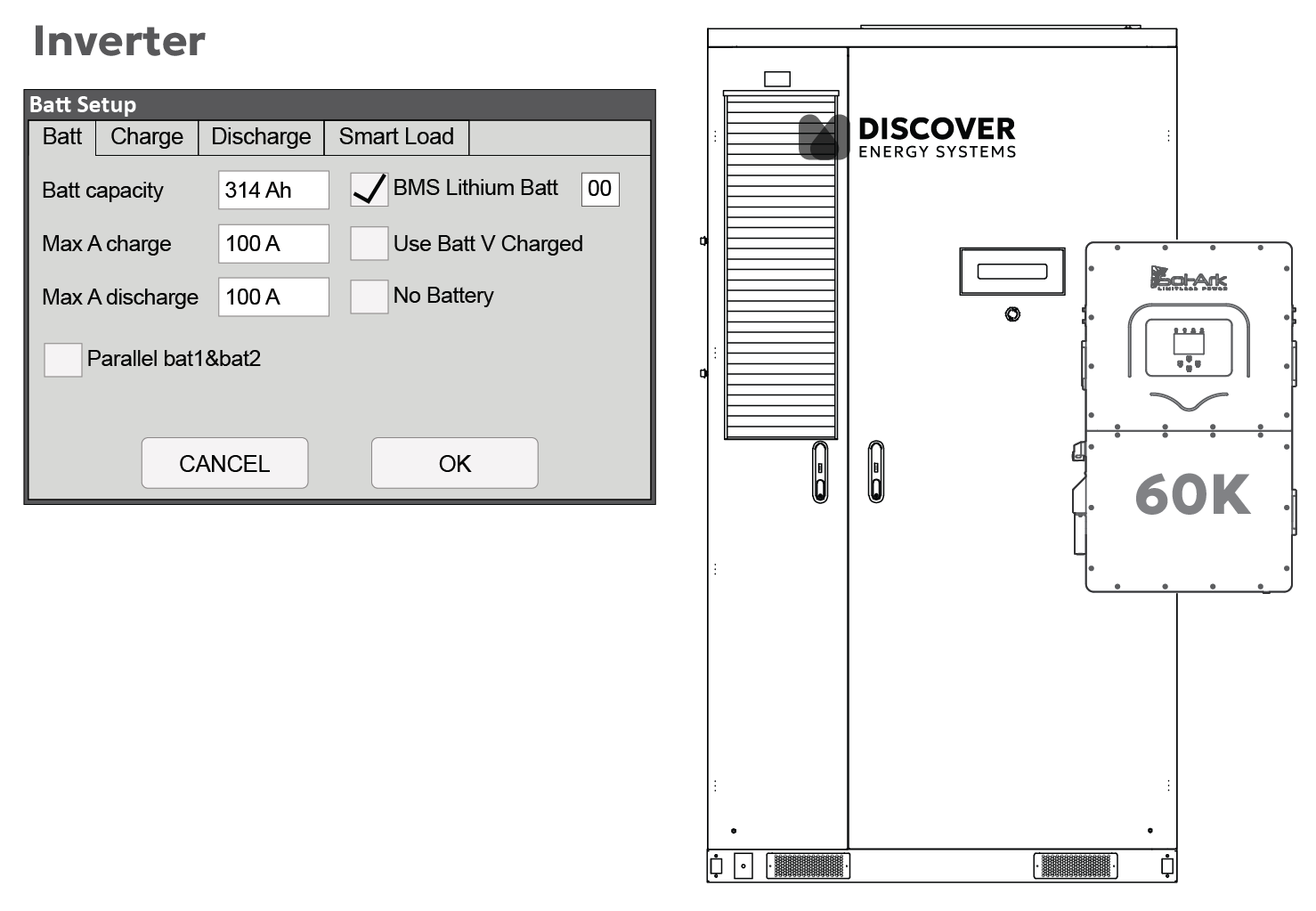
60 kW/209 kWh - One 60K-3P Inverter, One CAB-210
Refer to to the One Sol-Ark 3-Phase Inverter, One AES Cabinet system configuration.
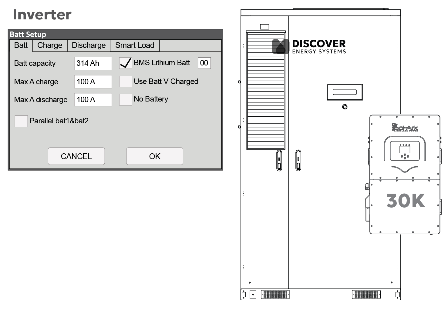
30 kW/104 kWh - One 30K-3P-208V Inverter, One CAB-106
Refer to to the One Sol-Ark 3-Phase Inverter, One AES Cabinet system configuration.
60 kW/418 kWh - Two 60K-3P Inverters, one CAB-210
Refer to the Two Sol-Ark 3-Phase Inverters, One AES Cabinet system configuration.
60 kW/418 kWh - One 60K-3P Inverter, Two CAB-210
Refer to to the One Sol-Ark 3-Phase Inverter, Two AES Cabinets system configuration.
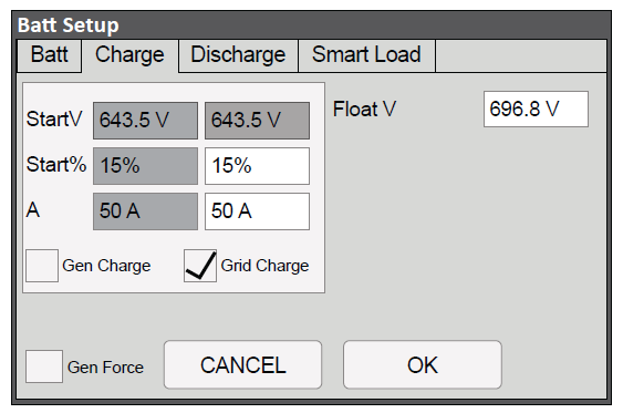
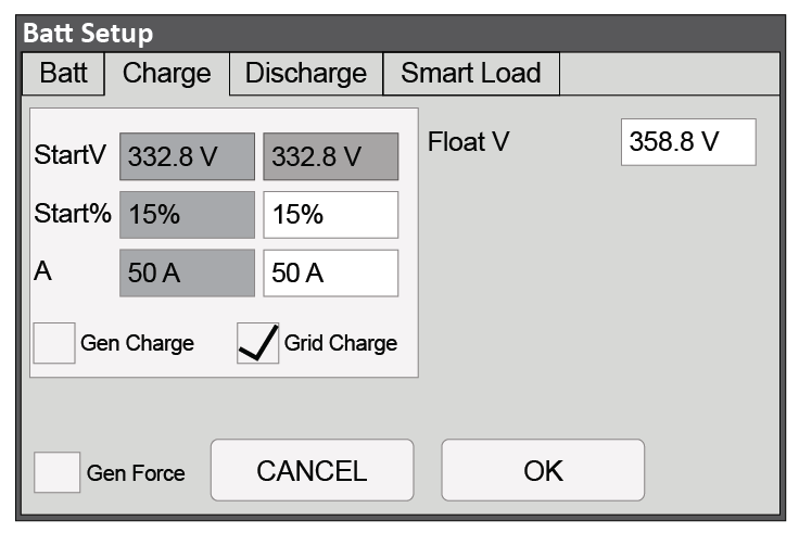
Charge Tab Configuration
Configure these settings if the system needs to charge the batteries using grid or generator power. While these settings are not mandatory, improper configuration may result in ineffective charging from these sources.
|
NOTE |
|---|
|
Certain values may be grayed out when the BMS Lithium Batt check box is selected. These values are typically ignored when closed-loop communication is active. However, it is recommended to configure them as a backup in case closed-loop communication is interrupted or deactivated for troubleshooting. To adjust grayed-out values, temporarily disable closed-loop mode by clearing the BMS Lithium Batt check box. Once the open-loop configurations are complete, be sure to re-enable closed-loop by selecting the check box. |
-
From the System Setup menu, select Battery Setup.
-
In the Batt Setup dialog box, open the Charge tab and configure the following settings.
The recommended values for the CAB-210 are shown in the image below.
The recommended values for the CAB-160 are shown in the image below.
The recommended values for the CAB-106 are shown in the image below.
-
Discharge Parameters. Set the battery state of charge (SOC) percentages and voltage values for Shutdown, Low Batt, and Restart. The recommended values are shown in the above image.
-
Batt Empty V. The recommended value is shown in the above image.
-
BMS Err Stop. When the BMS_Err_Stop check box is selected, the inverter will error and stop operating if closed-loop CAN communication with the cabinet is interrupted. While not mandatory, enabling this setting prevents the system from defaulting to open-loop mode (without warning) in the absence of closed-loop communication. Charging in open-loop for extended periods could lead to permanent damage to the battery.
|
NOTE |
|---|
|
Before changing tabs, always click OK to save the settings. After clicking OK, you must navigate back to the respective settings menu each time. |
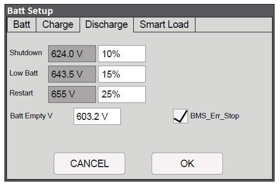
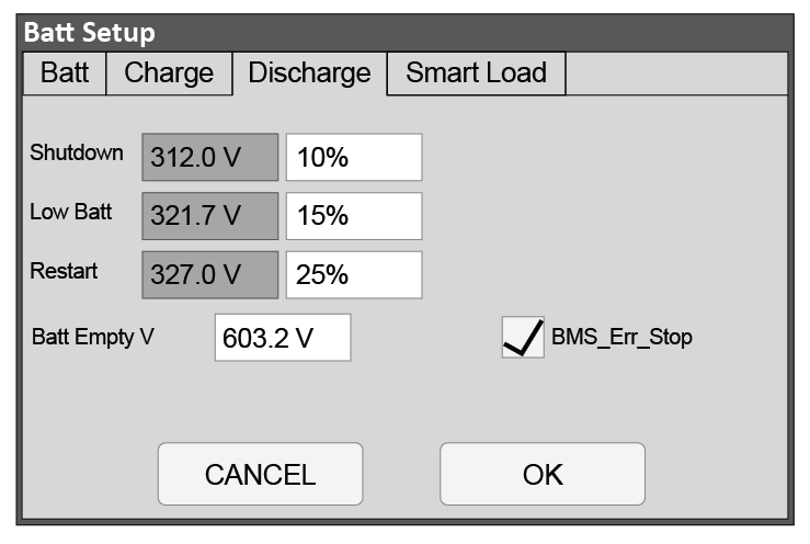
Discharge Tab Configuration
Configure the settings in the Discharge tab to protect the battery system from excessive discharge.
-
From the System Setup menu, select Battery Setup.
-
In the Batt Setup dialog box, open the Discharge tab and configure the following settings.
The recommended values for the AES 210HV are shown in the image below.
The recommended values for the CAB-106 are shown in the image below.
-
Discharge Parameters. Set the battery state of charge (SOC) percentages and voltage values for Shutdown, Low Batt, and Restart. The recommended values are shown in the above image.
-
Batt Empty V. The recommended value is shown in the above image.
-
BMS Err Stop. When the BMS_Err_Stop check box is selected, the inverter will error and stop operating if closed-loop CAN communication with the cabinet is interrupted. While not mandatory, enabling this setting prevents the system from defaulting to open-loop mode (without warning) in the absence of closed-loop communication. Charging in open-loop for extended periods could lead to permanent damage of the battery.
|
NOTE |
|---|
|
Before changing tabs, always click OK to save the settings. After clicking OK, you must navigate back to the respective settings menu each time. |