
|
|
|---|
|
ELECTRIC SHOCK AND FIRE HAZARD
Failure to follow these instructions may result in death or serious injury. |
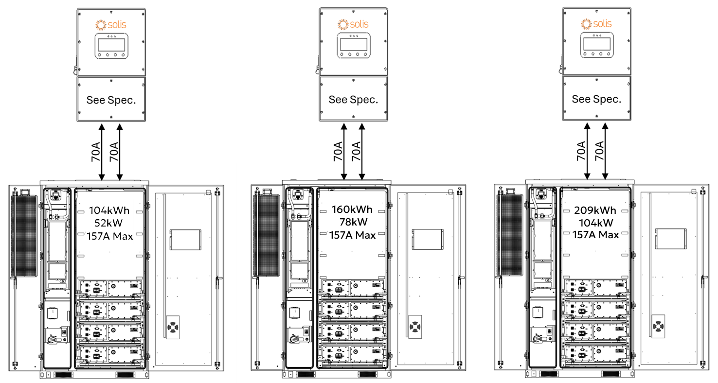
CAB-106, CAB-160, and CAB-210 Configurations
When paired with a single Solis S6-EH3P inverter, the AES Cabinet’s maximum continuous current limit is 157 A, operating within its rated 52 / 78 / 104 kW continuous output limit. Actual discharge performance depends on the inverter model’s battery-side power capacity, as shown below.
Full Load Duration
|
Inverter Model |
Battery Discharge Limit |
CAB-106 |
CAB-160 |
CAB-210 |
|---|---|---|---|---|
|
AC Output / Usable Storage / Estimated Runtime |
||||
|
S6-EH3P29.9K |
29.9 kW |
29.9 kW / 104 kWh / 3½ hours |
29.9 kW / 157 kWh / 5 hours |
29.9 kW / 209 kWh / 7 hours |
|
S6-EH3P30K |
30 kW |
30 kW / 104 kWh / 3½ hours |
30 kW / 157 kWh / 5 hours |
30 kW / 209 kWh / 7 hours |
|
S6-EH3P40K |
40 kW |
40 kW / 104 kWh / 2½ hours |
40 kW / 157 kWh / 4 hours |
40 kW / 209 kWh / 5 hours |
|
S6-EH3P50K |
50 kW |
50 kW / 104 kWh / 2 hours |
50 kW / 157 kWh / 3 hours |
50 kW / 209 kWh / 4 hours |
* Curtailed by the battery.
These autonomy estimates assume continuous full-power discharge and operation within safe continuous discharge parameters. Final performance should match the site's energy demand and load profile.
System Scalability – One Inverter, One AES Cabinet
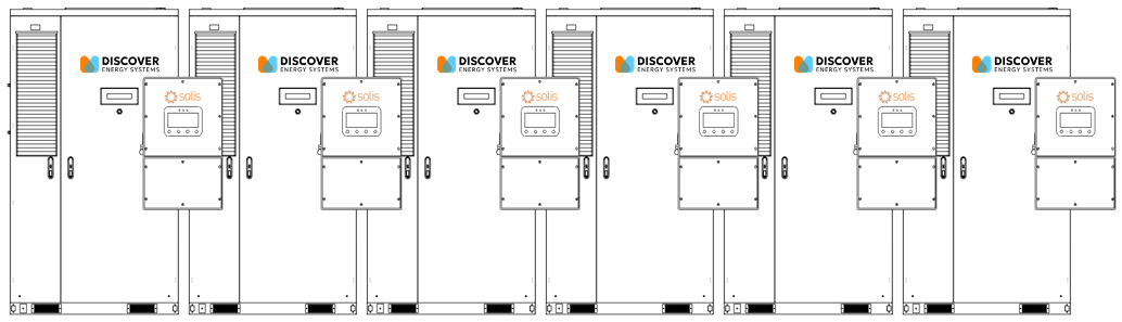
Each Solis S6-EH3P inverter is paired with one AES battery cabinet.
In this setup:
-
104 / 160 / 209 kWh of usable backup energy per inverter
-
Discharge power limited by the inverter model (29.9–50 kW)
-
Up to ten inverters can be connected in parallel on the backup side, providing 299-500 kW of continuous backup power and approximately 1.04-2.09 mWh of total backup energy (10 × 104 kWh / 10 × 157 kWh / 10 × 209 kWh).
Grid-Tied (Non-Backup) Scalability
The number of inverters or batteries is unlimited for non-backup use. Each inverter runs independently, allowing systems to scale as large as needed for energy shifting, peak shaving, or other grid-interactive applications.
DC Battery Wiring – One Inverter, One AES Cabinet
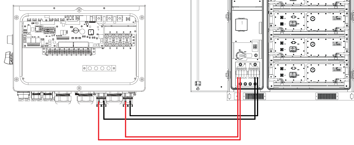
Each Solis S6-EH3P inverter has two battery input terminals, each rated up to 70 A. The AES Cabinet connects using:
-
Two positive and two negative 25 mm2 (#4 AWG) conductors
-
Each conductor is protected by a 70 A fuse in the AES Cabinet’s built-in DC distribution box
This setup ensures balanced current flow to each of the inverter’s internal DC/DC converters and, depending on the inverter model, supports continuous discharge of 29.9-50 kW.
Always follow AS/NZS 3000 Wiring Rules and the local authority having jurisdiction for conductor sizing, 1,000 Vdc insulation rating, and proper torque values. Verify polarity before energising the system.
Communication – One Inverter, One AES Cabinet
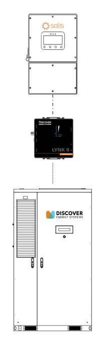
In a one-to-one configuration, the AES Cabinet communicates with the Solis inverter through the LYNK II Gateway, enabling real-time, managed (closed-loop) control.
-
Use standard CAT6 or higher Ethernet cables, wired in a straight-through configuration with RJ45 plugs on both ends.
-
Connect one cable from the LYNK II’s CAN port to the Solis inverter's BMS1 port.
-
Connect a second cable from the LYNK port on the LYNK II Gateway to the J3/J4 port on the AES Cabinet’s High Voltage Box. On most AES Cabinets, a CAT6 cable is already connected to the J3 port on the AES Cabinet’s High Voltage Box and is accessible from the LYNK II.
This communication link enables the inverter to receive live battery data, including state of charge, voltage, current, temperature, and charge/discharge limits, for safe, accurate, and optimized operation.