
Single Battery Installation Procedure
|
|---|
ELECTRIC SHOCK AND FIRE HAZARD
Failure to follow these instructions may result in injury. |
Install equipment following the standards set by the local authority having jurisdiction. The following instructions assume the battery and DC load have been attached to the wall.
Disconnect the cover plate protecting the positive and negative terminals.
Prepare the load and battery for wiring.
If the load is wired to a power source, open the disconnect and set the load OFF.
Use a DMM or other voltage measuring device to confirm the circuit is de-energized.
If the circuit in which the battery is installed has a disconnect, open the disconnect to isolate the battery.
Set both the battery BMS and the breaker to the OFF position.
Use a DMM or other voltage measuring device to confirm the circuit is de-energized.
Wire the load.
Use the HELIOS ESS Terminal Connector Set (950-0072) with 2/0 AWG (70 mm2) cables and appropriately sized ring terminals to create your own battery cables.
Or alternately, you can use the Battery to Inverter Power Cables 2/0 AWG (950-0070) to wire the batteries. Select the cable that is compatible with the expected power load.Ensure the cable connections are clean and in working order.
If required by the system, connect a circuit breaker between the load and battery.
Connect a positive power cable to the positive battery terminal on the load, and the other end of the power cable to the positive terminal on the circuit breaker.
Connect a negative power cable to the negative terminal on the load, and the other end of the power cable to the negative terminal on the circuit breaker.Connect the positive battery cable to the opposite positive terminal on the circuit breaker.
Connect the negative battery cable to the opposite negative terminal on the circuit breaker.
NOTE |
|---|
|
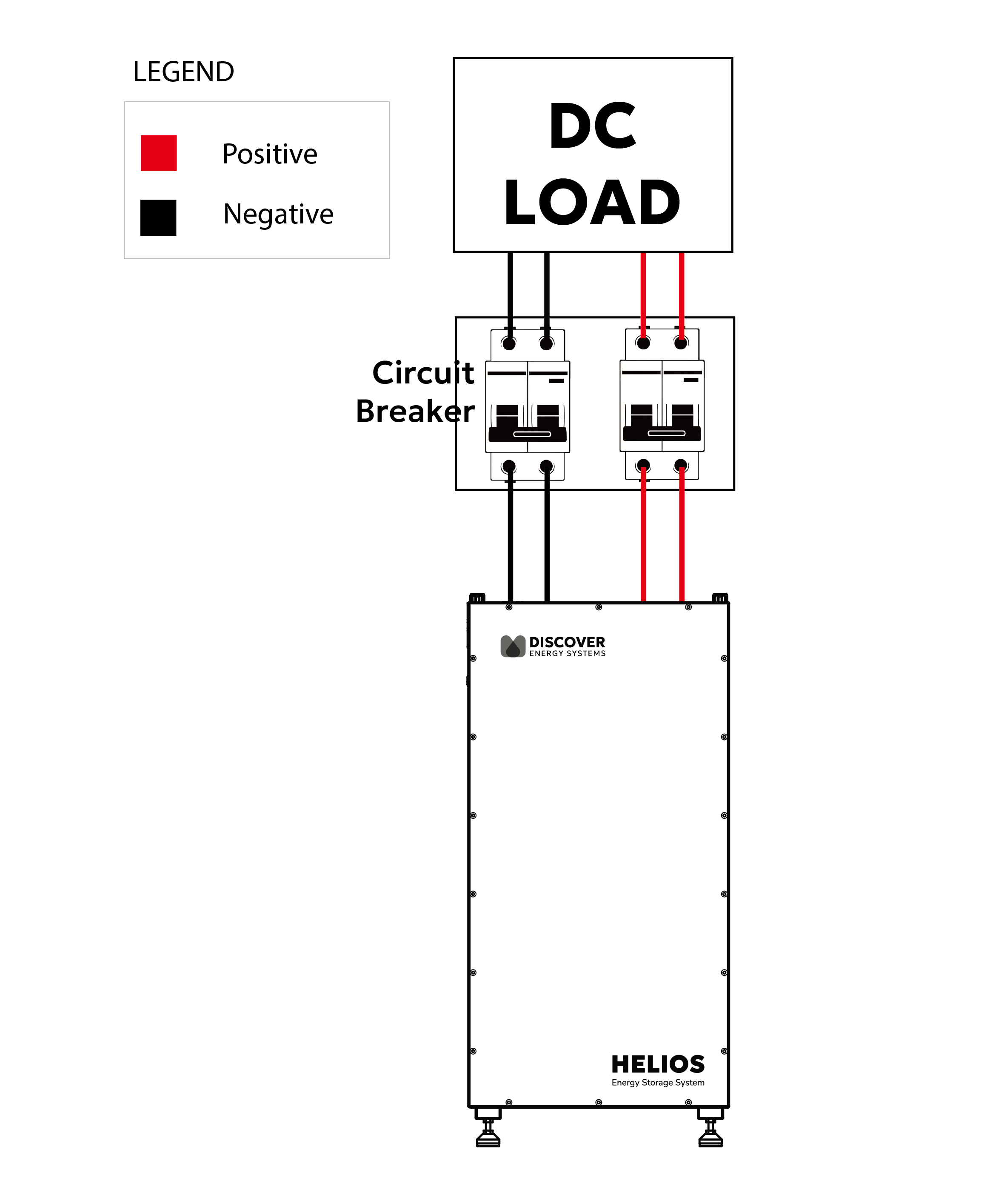
Wiring for One Battery
NOTE |
|---|
For multiple battery installation diagrams, refer to <link>Multiple Battery Installation Procedure (Parallel Wiring Kit) or More Than Three Battery Installation Procedure (Busbar). |
Connect the positive battery cables to the receiving pins of the positive battery terminals and push down to enable the connection. Refer to 9.4.3 Terminal Connections and Hardware.
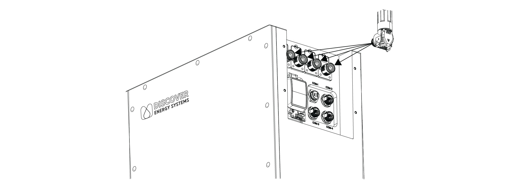
Connect Cables to Battery Terminals
Connect the negative battery cables to the receiving pins of the negative battery terminals and push down to enable the connection.
Connect the CAN communication cable. See Setting Up Closed-Loop Communication with the LYNK II Gateway or Setting Up Closed-Loop Communication Without the LYNK II Gateway.
Set the battery breaker ON (close).
Close the circuit breaker if it is open.
Set the battery BMS ON (ON/OFF key).
Re-attach the cover plate to protect the positive and negative battery terminals and to prevent the disconnection of sockets and terminals during operation.
NOTICE |
|---|
|