
|
NOTE |
|---|
|
Refer to the LYNK II Installation and Operation Manual (805-0033) for information on setting up the LYNK II Communication Gateway for your particular inverter-charger. |
If using the LYNK II Communication Gateway, connect the CAT6 communication cable from the inverter-charger to the LYNK device and then to each battery.
-
Attach the CAT6 or higher cable from the inverter to the LYNK II Communication Gateway’s CAN port.
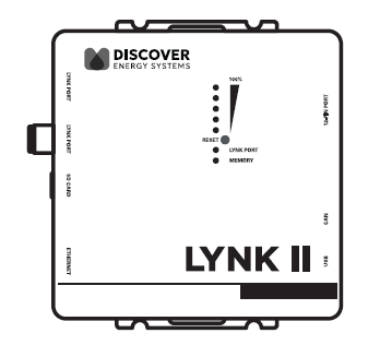
LYNK II Communication Gateway
-
Attach another CAT6 or higher cable to the LYNK II Communication Gateway’s LYNK port, then attach the other end of the CAT6 or higher cable to COM3 or COM4 (LYNK port) on the battery.
-
If paralleling multiple HELIOS ESS batteries, attach CAT6 or higher cables to the COM3/COM4 ports to connect all the batteries. Attach a CAT6 or higher cable to COM3 or COM4 (LYNK port) on the first battery to COM3/COM4 on the next battery, and so on, until all the batteries are connected.
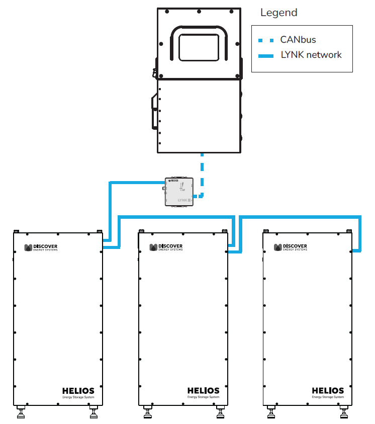
LYNK II Connection Between Inverter and Batteries
Testing and Verification of the LYNK Network
Perform network verification with the LYNK II Communication Gateway (950-0025).
-
If the LYNK Network Bus indication LED is illuminated, power and communication for the LYNK network are active.
-
Use LYNK ACCESS software through a computer to confirm the number of batteries in the LYNK network.
-
Use LYNK CLOUD to remotely monitor and troubleshoot the batteries.