
DC Cables
|
|
|---|
|
FIRE HAZARD Undersized cables can become hot and may potentially catch fire. Failure to follow these instructions may result in injury. |
To create your own cables, use 2/0 AWG (70 mm2) or 1/0 AWG (55 mm2) cables. Attach appropriately sized ring terminals on one end and a HELIOS ESS Terminal Connector (950-0072) on the opposite end. Choose the cables and ring terminals to accommodate the maximum voltage of any circuits sharing the same wiring space. Ensure they are sized to local codes and meet the following requirements.
-
Copper-stranded cable. DC cables must be stranded, copper, and rated 90 °C minimum. Terminate the cables on one side with lugs that fit the DC terminals on the inverter, and use the quick connect on the other side of the cable for the positive or negative battery terminal.
-
Minimum and equal cable lengths. Select a location that minimizes the length of battery cables to reduce voltage drop from the impedance leading to reduced performance. If installing multiple batteries in parallel, the length of all the battery cables should be the same.
-
Appropriate cable gauge. The cables should be capable of carrying the normally expected current, plus a margin of safety.
-
Proper polarity. Positive (+) is connected to positive (+), and negative (-) is connected to negative (-). Verify the polarity of all connections before energizing batteries.
|
NOTE |
|---|
|
DC Protection
|
|
|---|
|
FIRE HAZARD
Failure to follow these instructions may result in injury. |
Each battery comes equipped with a 200 A integrated breaker. When multiple batteries are installed in parallel, additional DC overcurrent protection is recommended between the battery bank and load.
-
Appropriate size. Size the fuses and disconnects following local codes to protect the wiring in the system. The fuses and disconnects are required to open before the cable reaches its maximum current carrying capability.
-
Install protection. When installing battery protection, ensure the fuse and disconnect are located as close as possible to the battery. Local electrical codes may specify the maximum allowable distance.
This disconnect should be sized to accommodate the maximum expected electrical load of your system. Always consult with your local authority having jurisdiction (AHJ) to correctly size and select breakers that meet all applicable requirements for your specific application.
|
NOTE |
|---|
|
Terminal Connections and Hardware
Plug-and-pull quick connects are used to mate with the plug-and-pull terminals on the HELIOS ESS battery.
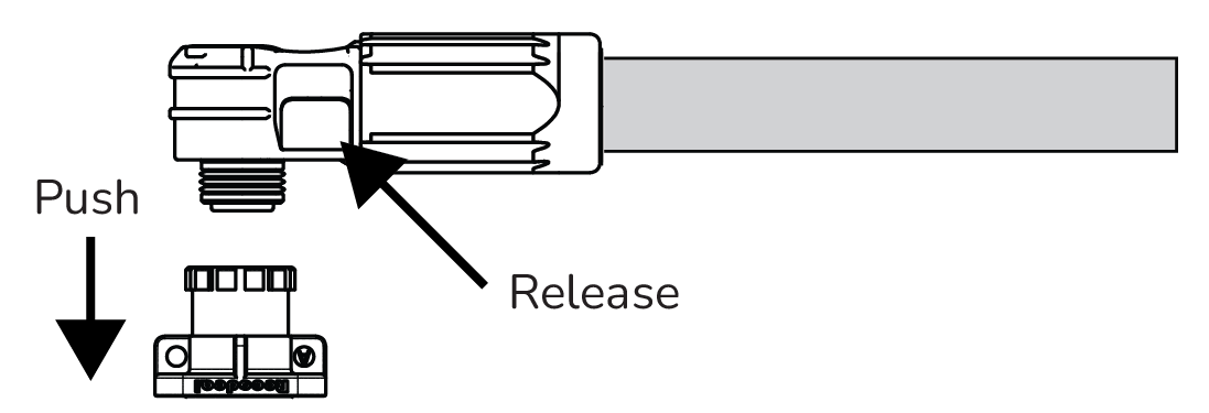
Plug-and-pull Quick Connect
-
Plug the connector into the plug-and-pull terminal.
-
Gently pull the connector to confirm it is snapped in place.
-
To disconnect, press the release button on the side of the connector.