
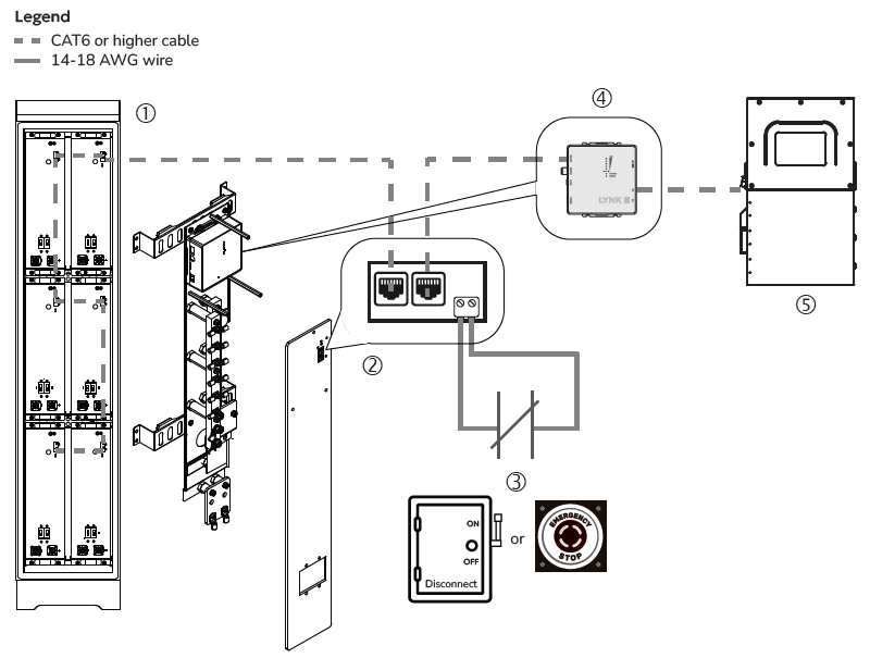
Figure 6, Slimline Enclosure Circuit
|
Item |
Description |
|---|---|
|
1 |
AES RACKMOUNT batteries are networked in a Slimline Enclosure. |
|
2 |
RPO board on the plexiglass busbar protector in the AES RACKMOUNT Slimline Enclosure. Wire the emergency switch to the terminals on the edge of the RPO board. NOTE: The terminals do not have a positive or negative. They need to be wired to opposite ends of the emergency switch. |
|
3 |
Normally Closed emergency switch (E-stop button or bladed lockable disconnect) |
|
4 |
(Optional) LYNK II or LYNK LITE Communication Gateway attached to the busbar mounting assembly on the Slimline Enclosure. It is not required to operate the E-stop/bladed lockable disconnect. |
|
5 |
Inverter It is not required to operate the E-stop/bladed lockable disconnect. |
Operation
RUN:
-
Use the power switch on each AES RACKMOUNT battery module to turn them all ON.
-
Close the circuit by turning the bladed lockable disconnect handle to ON or resetting (pulling up) the E-stop button.
-
After about 8 seconds, the battery modules become synchronized with the switch’s ON state.
SHUT DOWN: Push the E-stop button or crank the handle of the bladed lockable disconnect to OFF to open the circuit and turn OFF the batteries connected to the battery's LYNK network.