
The AES Cabinet is a high-voltage lithium iron phosphate (LiFePO₄) battery energy storage system designed for grid-tied, off-grid, and hybrid applications. It is built around a fully integrated cabinet containing battery modules, thermal management, safety systems, and communications.
Four to eight liquid-cooled battery packs are at the system’s core, with each battery pack configured as 1P52S (52 cells in series). Each pack delivers a nominal voltage of 166.4 Vdc. The battery packs are connected in series to provide a system voltage from 665.6 to 1331.2 Vdc (nominal), with a usable energy capacity from 209 to 418 kWh.
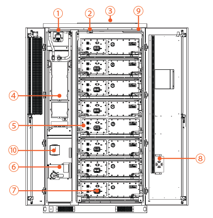
AES Cabinet, Front Doors Open
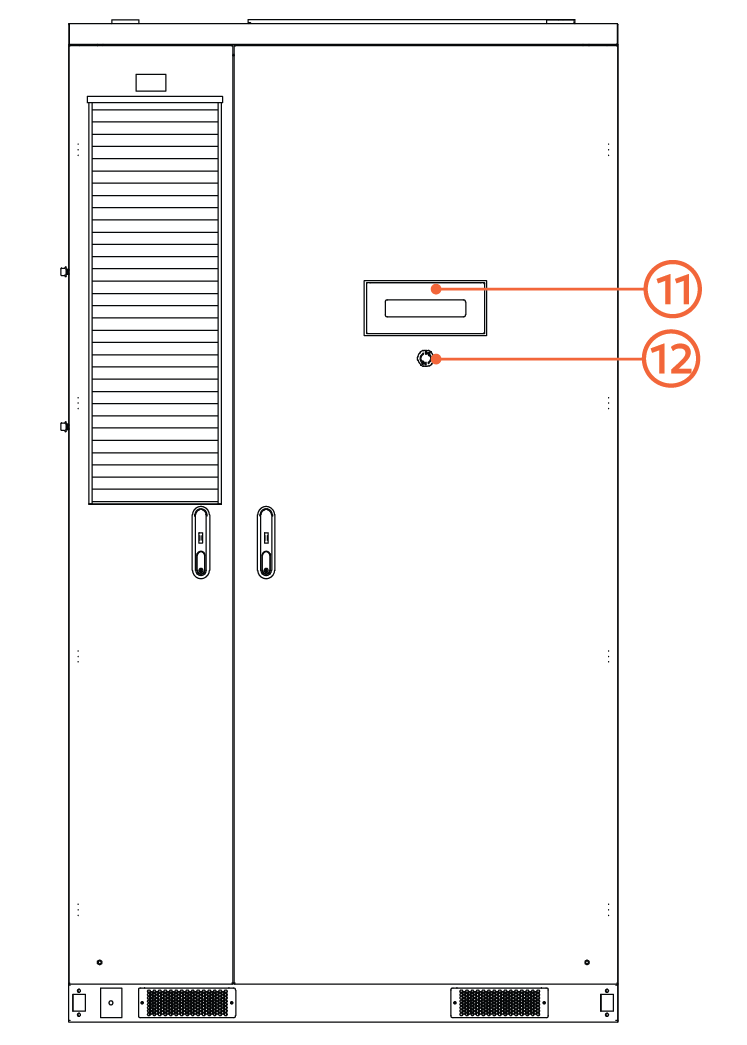
AES Cabinet, Doors Closed
|
No. |
Name |
Description |
|---|---|---|
|
1 |
Audible and Visual Fire Alarms |
In the event of a fire hazard, the battery cabinet activates the thermal suppression device and sounds an alarm. |
|
2 |
Heat and Smoke Detector |
Smoke detection triggers an alarm, while heat detection activates an alarm and the thermal suppression system. |
|
3 |
Passive Deflagration Vent |
Explosion control vents relieve pressure during thermal events by venting gases, which helps minimize the risk of explosion. |
|
4 |
Thermal Management System (TMS) |
The TMS manages heating and cooling for the battery cabinet. |
|
5 |
Battery Packs |
Energy storage units with integrated cell monitoring via the Battery Management Unit (BMU). Each pack features an aerosol fire suppression system and aerogel-based cell separation, ensuring advanced thermal runaway mitigation. |
|
6 |
High Voltage Box (HV Box) |
The HV Box manages power flow, protects the system, provides redundant control via UPS, and monitors the system through the Battery Control Unit (BCU). |
|
7 |
Manual Service Disconnect (MSD) |
Each battery pack is equipped with a Manual Service Disconnect (MSD). |
|
8 |
Dehumidifier |
The humidifier maintains humidity inside the sealed battery cabinet at an acceptable level. |
|
9 |
Cabinet Aerosol Fire Suppression Device |
If a high heat event is detected, the aerosol fire suppression system is automatically activated to quickly release an aerosol fire suppression agent. |
|
10 |
LYNK II Gateway |
The LYNK II Gateway facilitates communication between the battery cabinet BCU and external devices, such as inverters or cloud-based systems. |
|
11 |
LED Indicators |
The LEDs indicate the system operation status:
|
|
12 |
E-Stop |
Emergency stop switch for manual shutdown of the battery cabinet. |
How the System Works
-
Energy Storage & Delivery
The system stores energy from the grid, generator, or solar PV through a compatible high-voltage hybrid inverter. Stored DC energy is delivered to loads or exported through the inverter when required. The system supports charge and discharge operations within the defined voltage and current limits. -
Battery Management System (BMS)
Each pack includes a Battery Monitoring Unit (BMU) that collects voltage, temperature, and current data. These are managed by a central Battery Control Unit (BCU) in the High Voltage Box (HV Box). The BCU coordinates pack balancing, fault detection, and protection responses. It communicates with the inverter through the LYNK II Gateway over the CANbus network. -
Thermal Management System (TMS)
A liquid cooling and heating loop maintains optimal battery temperature. The chiller circulates a glycol-water coolant through heat exchange plates attached to each pack. The TMS switches between cooling, heating, and standby based on temperature readings. This protects against thermal runaway for performance in temperatures from –30°C to +55°C. -
Safety Systems
The AES Cabinet includes multi-layered safety features:-
Pack and cabinet-level aerosol fire suppression
-
Smoke and heat detectors
-
Emergency stop (E-Stop) circuit
-
Passive deflagration venting
-
Manual Service Disconnects (MSD) for physical isolation
-
When triggered, these systems shut down energy flow, isolate battery terminals, and suppress fire threats autonomously.
-
Communication & Monitoring
The integrated LYNK II Gateway enables closed-loop control with compatible inverters and provides cloud-based monitoring through LYNK Cloud. This allows operators to track system status, log data, and receive alerts for events or faults. -
Integration
The system is designed to operate with inverter brands such as Sol-Ark, Solis, and others that support the CANbus protocol. Power is routed through the integrated DC distribution panel, with pre-fused connections for a plug-and-play installation.