
|
|
|---|
|
ELECTRIC SHOCK
Failure to follow these instructions may result in death or serious injury. |
-
De-energize the Power Conversion equipment.
-
Switch the Battery Module Combiner Breaker to the OFF (Open) position.
-
Switch all Battery Modules to OFF.
-
Disconnect all the Amphenol SurLok Plus connectors from all the battery modules to isolate the Battery Module Combiner.
-
Protect the Battery Module terminals from short-circuiting and touch by covering them with terminal covers or electrically rated tape.
-
Disconnect the Power Conversion cables attached to the Battery Module Combiner.
-
Plan:
-
Where to locate the E-stop or bladed lockable disconnect. Typically, the emergency switch is located close to the meter.
-
Where to route the wires.
-
-
Access the top of the Battery Module Combiner and remove the top cover.
-
The RPO board is at the front of the Battery Module Combiner, where the RJ45 ports are.
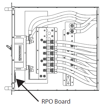
Figure 10, RPO Board on the Battery Module Combiner Box
-
Touch a grounded metal surface to remove the static electricity from your body.
-
Remove the screws securing the RPO board, then gently hold the top and bottom of the RPO board and dislodge it.
-
Once removed, you can access the wiring terminals of the RPO board.
-
Connect an E-stop button or a bladed lockable disconnect to the RPO board.
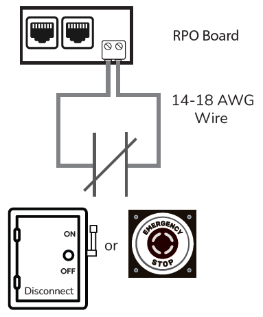
Figure 11, E-Stop Button/Bladed Lockable Disconnect Wiring