
|
|
|---|
|
ELECTRIC SHOCK
Failure to follow these instructions may result in death or serious injury. |
-
Isolate the Enclosure from external power sources by opening all the disconnects of externally connected equipment, such as inverters, battery chargers, and charge controllers.
-
Open and remove the Enclosure door. Be careful not to loosen the bonding wire between the door and the internal rack frame.
-
Turn off all the batteries and open all battery breakers.
-
Use a voltmeter to confirm no voltage across the positive and negative busbars. Over the Busbar Mounting Assembly is a sheet of plexiglass. Connected to the plexiglass is the RPO board.
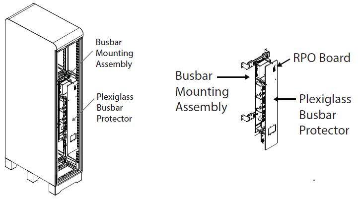
Figure 8, RPO Board on the Slimline Enclosure
-
Plan:
-
Where to locate the E-stop or bladed lockable disconnect. Typically the emergency switch is located close to the meter.
-
Where to route the wires. The choice of cables will determine if you need to run them through conduit or, if the wiring is specified for this purpose, can run them free air.
-
-
Remove the plexiglass busbar protector to access the wiring terminals of the RPO board.
-
Connect one end of the 14-18 AWG wire to one of the terminals on the RPO board and connect the other end of the wire to one side of the switch.
-
Connect another strand of 14-18 AWG wire to the open terminal on the RPO board and the open side of the switch.
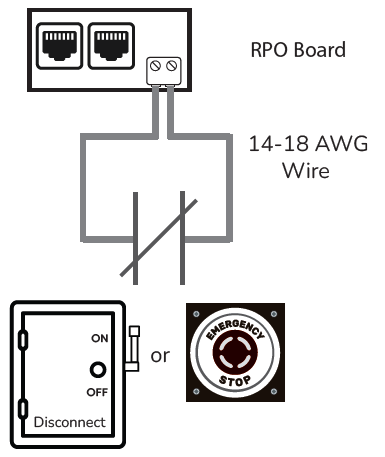
Figure 9, E-Stop Button/Bladed Lockable Disconnect Wiring