
After selecting the LV-BMS communication protocol for the LYNK II, complete the closed-loop configuration settings on the GROWATT inverter-charger. Ensure the Discover Lithium Batteries are networked with LYNK II and that the LYNK II is connected to the GROWATT CAN port.
If necessary, first configure GROWATT inverter-chargers to operate in parallel by establishing the inverter-charger master/slave relationships and phase designations before setting the parameters for battery operation. Configuring the master inverter-charger will cascade parameters and settings to the slave inverter-chargers.
Closed-loop Configuration
Refer to the latest Discover Energy Systems documentation for battery values and the latest GROWATT documentation for menu navigation and details on the setup procedure.
-
Set the Discover Lithium batteries to ON and set the inverter-charger to ON.
-
Using the touch screen and keypad on the inverter-charger, navigate to Main Screen >

-
Specify the battery settings according to the instructions in the tables that follow.
-
Touch a field to specify its value.
-
Touch the Up and Down arrows to scroll through the screens.
-
-
Exit and restart the inverter-charger.
|
NOTE |
|---|
|
If using multiple inverter-chargers, configure GROWATT inverter-chargers to operate in parallel before setting the battery operation parameters. |
|
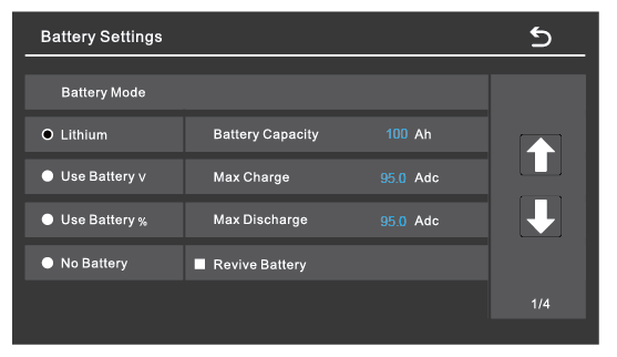
Battery Settings (page 1) |
|
|---|---|
|
Battery Mode |
Select the Lithium option to use the battery BMS. |
|
Refer to the electrical specifications in the battery manual to set the battery, charge, and discharge parameters. |
|
|
Battery Capacity |
Set to the number of Discover Lithium batteries x Ah capacity of each.
|
|
Max Charge |
Set to the lesser of the inverter’s max charge capacity, or the quantity of attached batteries, multiplied by the battery model’s specific max charge rating.
NOTE: Each HELIOS ESS battery is rated at a 200 A charge rate, but when connected in parallel, the maximum current is limited by internal busbars. For the recommended maximum current for paralleled HELIOS ESS, refer to the HELIOS Manual, Minimum Specifications for Battery Systems. |
|
Max Discharge |
Set to the lesser of the inverter’s max discharge capacity, or the quantity of attached batteries, multiplied by the battery model’s specific max discharge rating.
NOTE: Each HELIOS ESS battery is rated at a 200 A discharge rate, but when connected in parallel, the maximum current is limited by internal busbars. For the recommended maximum current for paralleled HELIOS ESS, refer to the HELIOS Manual, Minimum Specifications for Battery Systems. |
|
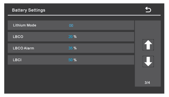
Battery Setting (page 3) |
|
|---|---|
|
Lithium Mode |
Set this value to 00. |
|
LBCO |
Specify the battery SOC for when to stop discharge — low battery cut-off (LBCO) — and when to allow discharge again — low battery cut-in (LBCI). |
|
LBCO Alarm |
|
|
LBCI |
|
Set other settings to match the user preferences or the particular use case.