
Whenever possible, using a closed-loop configuration is recommended with Discover batteries and Victron devices. However, using an open-loop configuration may be required if the closed-loop communication system encounters an issue, such as a failure of the LYNK II gateway, cables or connections, or the Victron device.
In such cases, you may have to set the system to open loop until the issue is resolved. The following describes how to set up open loop on Victron devices.
Setting up Open Loop on Victron Devices
You will need the latest firmware on all connected devices. The following presumes familiarity with VE Configure software. After setting the voltage-based open-loop parameters using the VE Configure 3 software, ‘send’ all parameters to the inverter-charger and GX device, and then restart the GX device.
VE Configure 3 Software
Inverter-Charger Configuration
Refer to the latest Discover Energy Systems documentation for battery values and the latest Victron documentation for details on menu navigation and the setup procedure.
-
Set the Discover Lithium batteries to ON and set the inverter to ON.
-
Connect your computer to the Victron GX device or inverter.
-
On the computer, start the VE Configure 3 software configuration tool.
-
Enable and disable parameter values according to the tables below.
-
Send the parameters to the Victron inverter-charger and GX device.
-
Toggle the On/Off/Charger Only switch to turn the inverter OFF and ON.
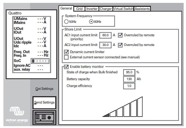
VE Configure 3 > General Tab
|
General Tab |
AES RACKMOUNT
|
HELIOS ESS
|
|---|---|---|
|
[AC1] Overruled by remote (1) |
Enable |
|
|
[AC2] Overruled by remote (1) |
Enable |
|
|
Dynamic current limiter |
Enable |
|
|
External current sensor connected |
Disable |
|
|
Enable battery monitor |
Enable |
|
|
State of charge when Bulk finished (2) |
95% |
|
|
Battery capacity |
Number of batteries x 100 Ah |
Number of batteries x 314 Ah |
|
Charge efficiency (2) |
1.00 |
|
(1) Enable is recommended.
(2) Precautionary settings ignored during normal operation and communication with Discover lithium batteries.
VE Configure 3 > Inverter Tab
|
Inverter Tab |
AES RACKMOUNT
|
HELIOS ESS
|
|---|---|---|
|
DC input low shutdown (1) |
48.0 V |
|
|
DC input low restart (2) |
52.0 V |
|
|
DC input low pre-alarm (3) |
49.5 V |
|
|
Enable AES (4) |
Disable |
|
(1) The lowest operating voltage allowed. Increase voltage as required.
(2) Restart voltage after DC input low shutdown. Recommend setting to the minimum value (minimum varies according to the DC Input low shutdown value).
(3) 49.5 V / 24.75 V value (approximately 10% SOC) will trigger a low battery warning. Increase or decrease as preferred.
(4) ‘Enable AES’ has no relation to either the AES RACKMOUNT or HELIOS ESS battery. Refer to Victron manuals for information on the AES setting and function.
VE Configure 3 > Charger Tab
|
Charger Tab |
AES RACKMOUNT
|
HELIOS ESS
|
|---|---|---|
|
Enable charger |
Enable |
|
|
Battery Type (1) |
Blank |
|
|
Lithium Batteries (1) |
Enable |
|
|
Charge Curve (1) |
Select: Fixed |
|
|
Absorption Voltage (1) |
55.2 V |
|
|
Float Voltage (1) |
53.6 V |
|
|
Charge Current |
Number of batteries x 95 A |
Number of batteries x 200 A |
|
Repeated absorption time (1)(2) |
1.0 < 3.0 Hr |
|
|
Repeated absorption interval(1) |
7.0 Days |
|
|
Absorption time (1)(2) |
1.00 < 3.0 Hr |
|
(1) Precautionary settings are ignored during normal operation and communication with Discover lithium batteries.
(2) The recommended minimum is 1.0 hour. Multiple batteries may require a longer time to achieve a smooth completion of the charge.
|
NOTE |
|---|
|
Confirm the Float Voltage after installation of any Victron ’Assistants’, and if necessary, set the Float Voltage back to 53.6 V. |
MPPT Charge Controller Configuration
During normal operation, the MPPT charge characteristics are governed by the Victron GX device in a closed-loop configuration based on data and charge requests provided by the connected Discover Lithium battery.
When closed-loop communication has failed, the MPPT needs to be reset and reconfigured to use open-loop communication. Simply cycling the power does not reset the charger.
To remove the charger from a closed-loop system and use it in a system without a BMS:
The Victron Connect Bluetooth App is used to configure, monitor, and diagnose Victron MPPT Charge Controller products equipped with Bluetooth. |
Victron Connect Bluetooth App |
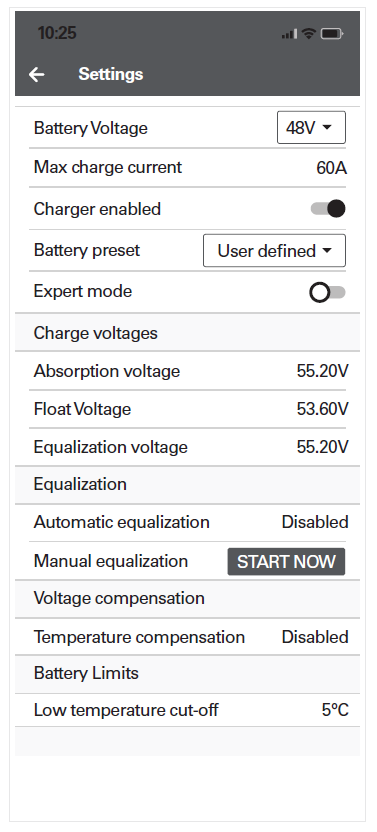
Victron Connect Bluetooth App > Device List > Victron MPPT > Settings > Battery
|
MPPT Battery Settings Menu |
AES RACKMOUNT
|
HELIOS ESS
|
|---|---|---|
|
Battery voltage |
48 V |
|
|
Max charge current (1) |
Number of batteries x 95 A |
Number of batteries x 200 A |
|
Charger enabled |
Enabled |
|
|
Battery preset |
User Defined |
|
|
Expert mode |
Disabled |
|
|
Absorption voltage |
55.2 V |
|
|
Float voltage |
53.6 V |
|
|
Equalization voltage |
55.2 V |
|
|
Automatic equalization |
Disabled |
|
|
Temperature compensation |
Disabled |
|
|
Low temperature cut-off |
< 4°C (39.2°F) |
|
|
Maximum absorption time (2) |
1.0 < 3.0 Hr |
|
(1) May be set to a lower value if necessitated by charger controller size.
(2) When editing battery presets, set the duration of the absorption period, which occurs after the bulk charge interval. The recommended minimum is 1.0 hour. Multiple batteries may require a longer time to achieve a smooth completion of charge.