
Connecting the LYNK II Phoenix Connector
This page describes how to wire the Phoenix Connector on the LYNK II to the Schneider Electric Insight device.
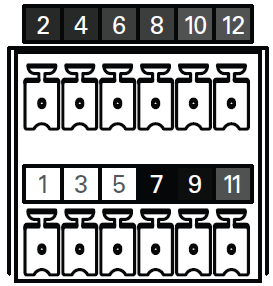
Pins on the LYNK II Phoenix 12-pin Connector
12-Pin Connector Layout | |||||
|---|---|---|---|---|---|
2 | 4 | 6 | 8 | 10 | 12 |
RELAY 3 COM | RELAY 3 N/O | RELAY 2 N/O | RELAY 2 COM | RELAY 1 N/O | RELAY 1 COM |
1 | 3 | 5 | 7 | 9 | 11 |
CAN HIGH | CAN LOW | CAN GND | POWER GND | POWER Vin (13-90V) | RELAY 1 N/C |
20 AWG wires are recommended to connect the CAN pins on the LYNK II, 12-pin connector to the CAN pins of either the 12-pin connector of InsightHome or the 26-pin connector of InsightFacility.
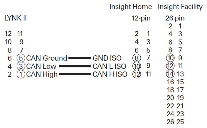
Mapping LYNK II Phoenix Connector Pins to Insight Device Pins
Top Row | Bottom Row | |||
|---|---|---|---|---|
1 | Digital Output (0-40 Vdc) | 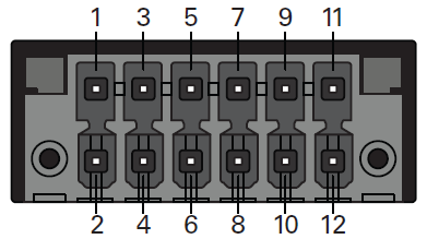 InsightHome 12-pin connector | 2 | Digital Input 1 (12 Vdc) |
3 | GND | 4 | Digital input 2 (12 Vdc) | |
5 | Do not connect | 6 | Do not connect | |
7 | GND ISO | 8 | GND ISO | |
9 | RS485 A ISO | 10 | CAN L ISO | |
11 | RS485 B ISO | 12 | CAN H ISO | |
Top Row | Bottom Row | |||
|---|---|---|---|---|
1 | GND | 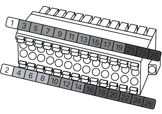 InsightFacility 26-pin connector | 2 | 9-24 Vdc power input |
3 | 0-10 Vdc analog input 1 | 4 | GND | |
5 | 0-10 Vdc analog input 2 | 6 | 12 Vdc digital input 1 | |
7 | GND | 8 | 12 Vdc digital input 2 | |
9 | 4-20 mA input 1 | 10 | ISO1 CAN GND | |
11 | 4-20 mA input 2 | 12 | ISO1 CAN L | |
13 | GND | 14 | ISO1 CAN H | |
15 | Relay 1 N/O | 16 | ISO2 RS485 GND | |
17 | Relay 1 COM | 18 | ISO2 RS485 1A | |
19 | Relay 1 N/C | 20 | ISO2 RS485 1B | |
21 | Relay 2 N/O | 22 | ISO2 RS485 GND | |
23 | Relay 2 COM | 24 | ISO2 RS485 2A | |
25 | Relay 2 N/C | 26 | ISO2 RS485 2B | |