
|
|
|---|
|
HIGH VOLTAGE HAZARD
Failure to follow these instructions may result in death or serious injury. |
|
Cabinet ID: |
|
|
Technician: |
|
|
Date: |
|
Preparation
-
Download and install the latest version of LYNK ACCESS onto a Windows laptop.
-
Connect a USB Type A to USB mini-B cable between the laptop and the LYNK II Gateway inside the battery cabinet.
-
Start the LYNK ACCESS software.
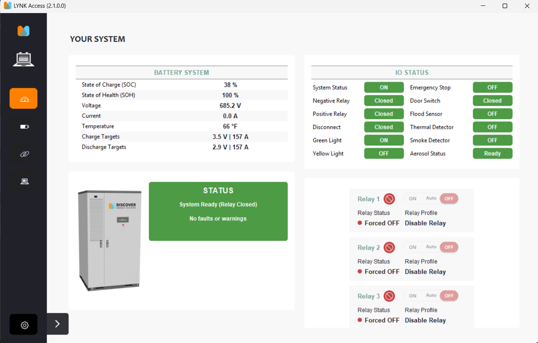
✅ Auxiliary Power Power-up Test
The dehumidifier is part of the auxiliary systems and powered through the 24 V UPS.
|
Task |
Pass/Fail |
Notes |
|---|---|---|
|
Check that the auxiliary power supply voltage is normal.
|
☐ / ☐ |
|
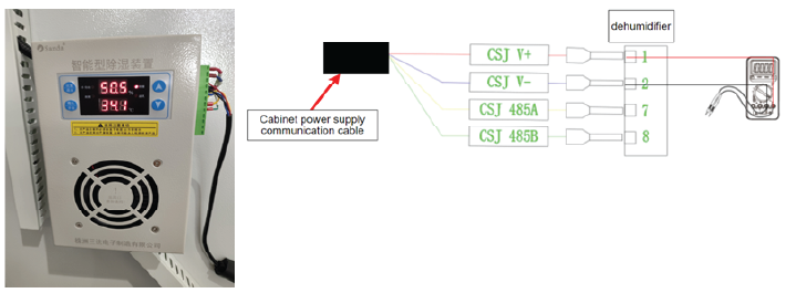
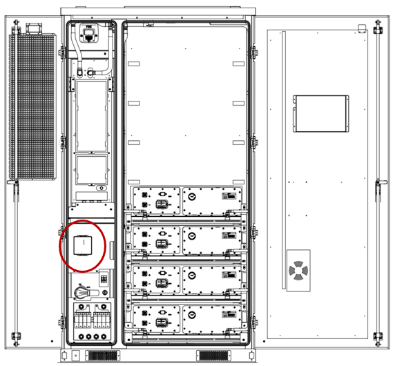
Dehumidifier Voltage testing
✅ Cabinet Door Indicator Light Test
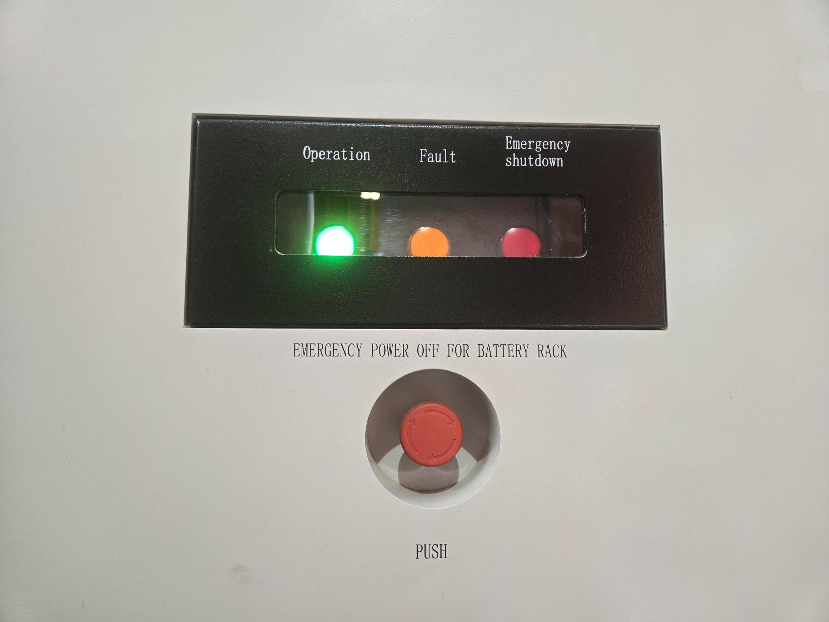
Indicator lights |
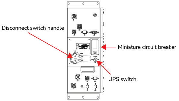
High Voltage Box |
|
Task |
Pass/Fail |
Notes |
|---|---|---|
|
Start up the system
The green indicator light flashes and then turns a solid green. |
☐ / ☐ |
|
|
Check the emergency stop indicator light
The red indicator light turns ON, indicating an emergency stop condition. Faults appear in LYNK ACCESS. |
☐ / ☐ |
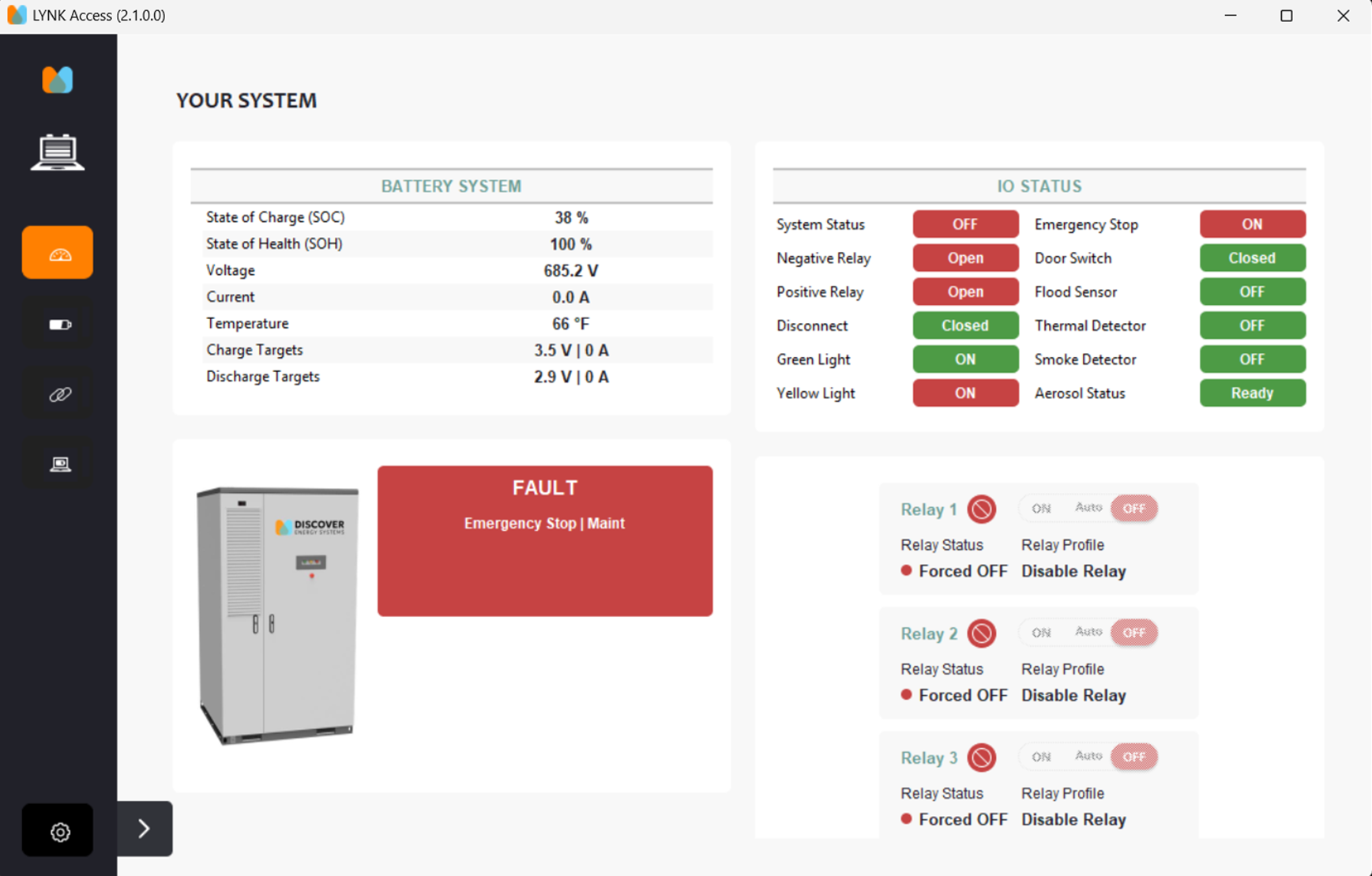
LYNK ACCESS |
|
Shut down the system
All the lights turn off indicating the battery has shut down. |
☐ / ☐ |
|
✅ Thermal Management System Test

Thermal Management System
|
Task |
Pass/Fail |
Notes |
|---|---|---|
|
☐ / ☐ |
|
✅ UPS Test
|
Task |
Pass/Fail |
Notes |
|---|---|---|
If the green operation indicator light continues flashing or remains ON, the UPS backup function is normal. |
☐ / ☐ |
|
If the green operation indicator is off, the UPS shutdown function is normal. |
☐ / ☐ |
|
If the green operation indicator light is flashing/ON, the UPS cold start function is normal. |
☐ / ☐ |
|
If the green operation indicator light is flashing/ON, the operation is normal. |
☐ / ☐ |
|
✅ Fire Suppression System Test
Preparation
|
Task |
Pass/Fail |
Notes |
|---|---|---|
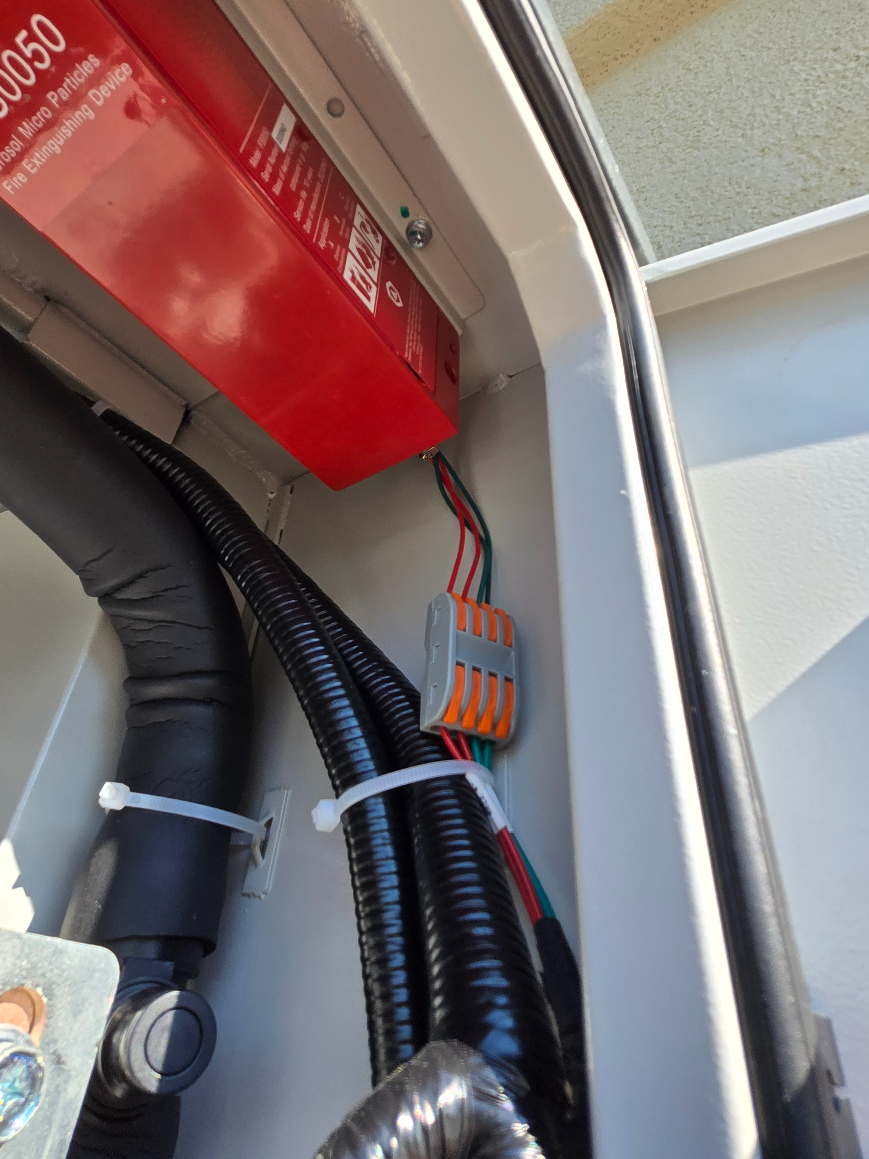
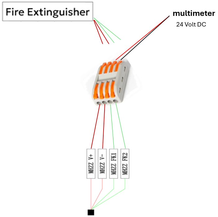
Disconnect Aerosol Canister Wires from Top of WAGO Connector The bottom wires of the WAGO connector will have 24V power and signal. |
☐ / ☐ |
|
|
|
|---|
|
INJURY HAZARD
Failure to follow these instructions may result in injury. |
Smoke Alarm Test
|
Task |
Pass/Fail |
Notes |
|---|---|---|
|
☐ / ☐ |
|
High Temperature Alarm Test
|
|
|---|
|
INJURY HAZARD
Failure to follow these instructions may result in injury. |
|
Task |
Pass/Fail |
Notes |
|---|---|---|
|
At the end of this procedure, reconnect the wires to the WAGO connector ensuring each wire is inserted in its original location.
|
☐ / ☐ |
|
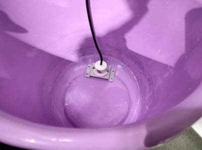
✅ Flood Sensor Function Test
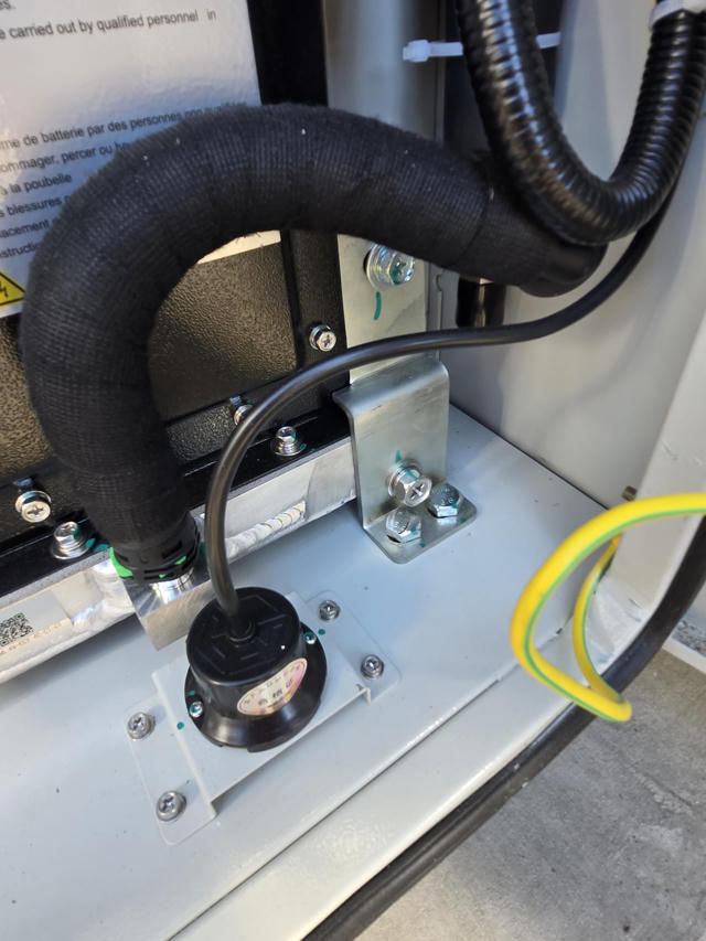
Flood Sensor
|
Task |
Pass/Fail |
Notes |
|---|---|---|
|
☐ / ☐ |
|