
Connecting to the Insight Device
This page describes how to wire the LYNK II CAN port to the Schneider Electric Insight device.
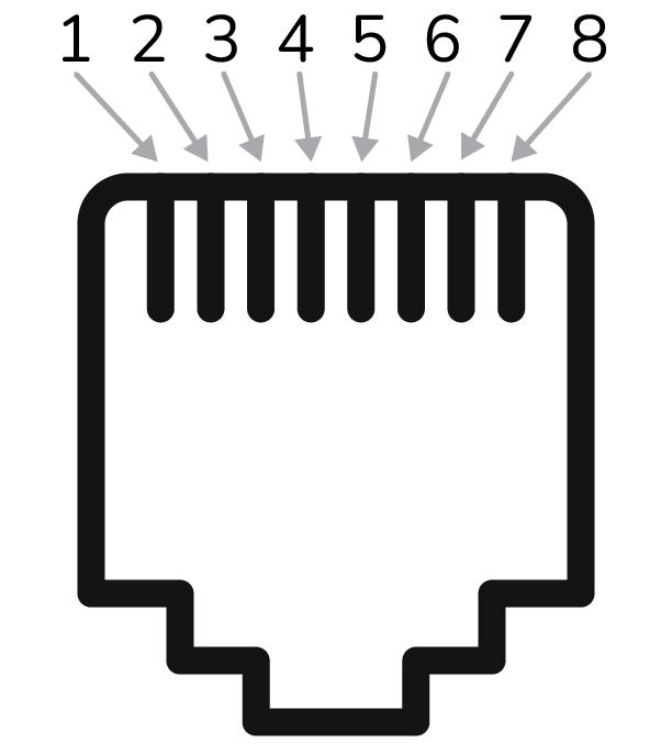
CAN Port Pin Map RJ45 Terminal Connector
PIN | DESCRIPTION |
|---|---|
1 | — |
2 | — |
3 | — |
4 | CAN Low |
5 | CAN High |
6 | Ground |
7 | (brown and white striped wire) |
8 | (brown colored wire) |
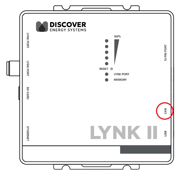
CAN Port on the LYNK II Gateway
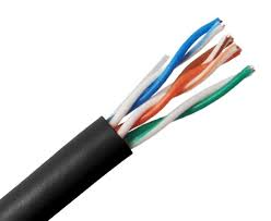
Use a CAT6 or higher cable to connect the pins on the LYNK II CAN port to the CAN pins of either the 12-pin connector of InsightHome or the 26-pin connector of InsightFacility.
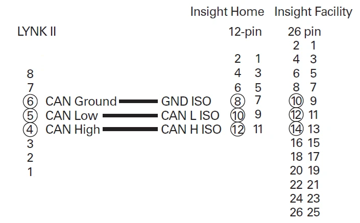
Mapping LYNK II CAN Port Pins to Insight Device Pins
Top Row | Bottom Row | |||
|---|---|---|---|---|
1 | Digital Output (0-40 Vdc) | 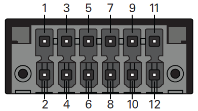 InsightHome 12-pin connector | 2 | Digital Input 1 (12 Vdc) |
3 | GND | 4 | Digital input 2 (12 Vdc) | |
5 | Do not connect | 6 | Do not connect | |
7 | GND ISO | 8 | GND ISO | |
9 | RS485 A ISO | 10 | CAN L ISO | |
11 | RS485 B ISO | 12 | CAN H ISO | |
Top Row | Bottom Row | |||
|---|---|---|---|---|
1 | GND | 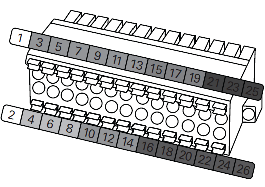 InsightFacility 26-pin connector | 2 | 9-24 Vdc power input |
3 | 0-10 Vdc analog input 1 | 4 | GND | |
5 | 0-10 Vdc analog input 2 | 6 | 12 Vdc digital input 1 | |
7 | GND | 8 | 12 Vdc digital input 2 | |
9 | 4-20 mA input 1 | 10 | ISO1 CAN GND | |
11 | 4-20 mA input 2 | 12 | ISO1 CAN L | |
13 | GND | 14 | ISO1 CAN H | |
15 | Relay 1 N/O | 16 | ISO2 RS485 GND | |
17 | Relay 1 COM | 18 | ISO2 RS485 1A | |
19 | Relay 1 N/C | 20 | ISO2 RS485 1B | |
21 | Relay 2 N/O | 22 | ISO2 RS485 GND | |
23 | Relay 2 COM | 24 | ISO2 RS485 2A | |
25 | Relay 2 N/C | 26 | ISO2 RS485 2B | |