
Setting Closed-Loop Configuration on the Luxpower Inverter
After selecting the Luxpower communication protocol for the LYNK II, complete the closed-loop configuration on the Luxpower inverter. Confirm the Discover Lithium batteries are networked with LYNK II and that the LYNK II is connected to the Luxpower CAN port.
NOTE |
|---|
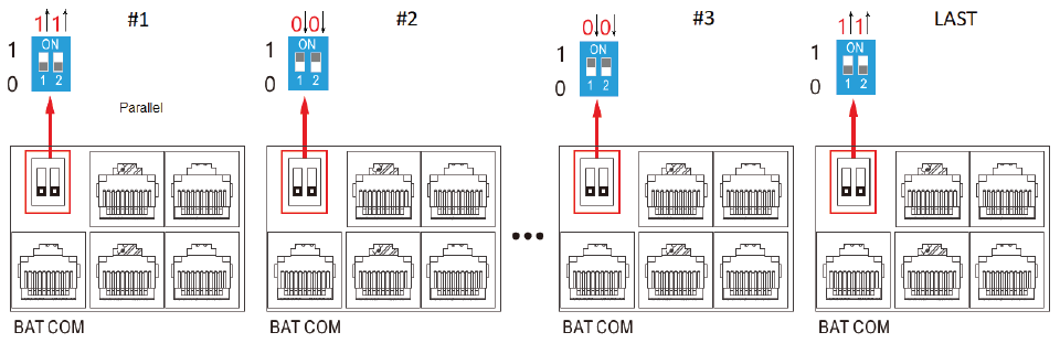 Pin Settings for Multiple Luxpower Inverters |
Refer to the latest Discover Energy Systems documentation for battery values and the latest Luxpower documentation for menu navigation and details on the setup procedure.
Set the Discover Lithium batteries to ON and set the inverter to ON.
Using the inverter touch screen interface, touch the
 Gear icon to set the properties as indicated in the following tables.
Touch the
 Up and
  Down buttons to scroll through screens.
Touch the
 Set button to save changes on a screen.
NOTE |
|---|
Depending on your system and particular use case, there may be other settings that require configuration. Refer to the inverter manual for information on these settings. |
![]() > Advanced
> Advanced
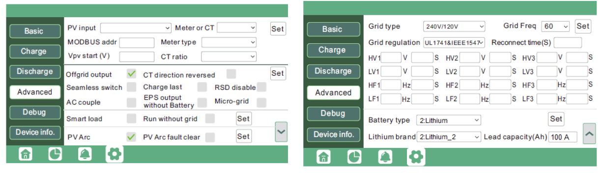
Advanced Screen 1, Screen 2
Advanced (Screen 2) | |
|---|---|
Battery Type | Select 2: Lithium. |
Lithium brand | Select Lithium_2. |
![]() > Charge
> Charge
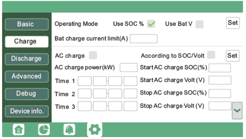
Charge Screen 1
Charge (Screen 1) | AES RACKMOUNT 48-48-5120 / 48-48-5120-H | HELIOS ESS 52-48-16000 |
|---|---|---|
Operating Mode | Select the Use SOC % check box. | Select the Use SOC % check box. |
Bat charge current limit (A) | 95 A x number of batteries | 200 A x number of batteries NOTE: Each HELIOS ESS battery is rated at a 200 A charge rate, but when connected in parallel, the maximum current is limited by internal busbars. For the recommended maximum current for paralleled HELIOS ESS, refer to the HELIOS Manual, Minimum Specifications for Battery Systems. |
![]() > Discharge
> Discharge
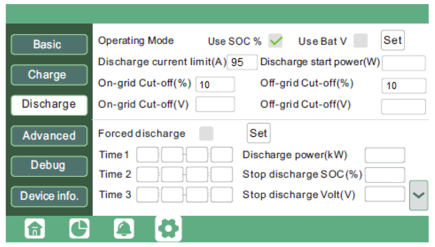
Discharge Screen 1
Discharge (Screen 1) | AES RACKMOUNT 48-48-5120 / 48-48-5120-H | HELIOS ESS 52-48-16000 |
|---|---|---|
Operating Mode | Select the Use SOC % check box. | Select the Use SOC % check box. |
Discharge current limit (A) | 95 A x number of batteries | 200 A x number of batteries |
On-grid cut-off (%) | The recommended value is 10% or more. | The recommended value is 10% or more. |
Off-grid cut-off (%) |